|
Have you ever wondered how professional
cylinder head porters and designers come up with their high-flowing
ports and runner shapes? Naturally it takes considerable experience
behind a die grinder and flowbench. But it also the right
tools and techniques. One of those techniques is making a
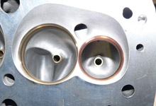
mold of the port. Port molds offer up a variety of analytical
opportunities by enabling the porter to see the entire runner
as a physical shape rather than as an empty cavity. The mold
of course also allows visualization of parts of the runner
that cannot be seen by looking into the port, such as the
short-side radius or transition around the valve guide. The
mold can be analyzed for shape, cut in various areas to measure
port dimensions, and even compared to molds taken earlier
or later in the process or versus other ports on the head.
It's a seemingly sophisticated technique that in reality is
very easy to do and only costs about $25 in materials. If
you port your own heads we highly recommend you take a mold.
If you port heads for customers a mold can be a great way
to periodically check your work on subsequent heads.

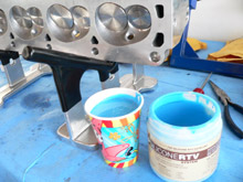
 We've all used Silicone RTV as a gasket maker and have
marveled at how it takes a firm shape. That's basically
what we're using to make the mold. Silicone RTV (Room
Temperature Vulcanizing) mold kits are available from
hobby shops like TAP
Plastics. This kit is rated as "25 Shore A"
mold rubber - meaning it yields a low shrinkage, dimensionally
stable and elongation-resistant mold.
We've all used Silicone RTV as a gasket maker and have
marveled at how it takes a firm shape. That's basically
what we're using to make the mold. Silicone RTV (Room
Temperature Vulcanizing) mold kits are available from
hobby shops like TAP
Plastics. This kit is rated as "25 Shore A"
mold rubber - meaning it yields a low shrinkage, dimensionally
stable and elongation-resistant mold.
|
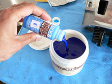
 The 1lb kit is good for making one intake and one exhaust
port. The two parts are mixed right before you are ready
to pour the mold. The mix consists of a 9:1 ratio by volume
of base component (side A) and catalyst (side B). The
catalyst is added directly to white base container.
The 1lb kit is good for making one intake and one exhaust
port. The two parts are mixed right before you are ready
to pour the mold. The mix consists of a 9:1 ratio by volume
of base component (side A) and catalyst (side B). The
catalyst is added directly to white base container. |

 The two parts must be mixed thoroughly until the material
is a light blue consistency throughout. White streaks
mean the base is not mixed well, this will result in a
mold with nooks and crannies.
The two parts must be mixed thoroughly until the material
is a light blue consistency throughout. White streaks
mean the base is not mixed well, this will result in a
mold with nooks and crannies. |
 You only have about 30 minutes of working time before
the silicone starts to cure. A "green" catalyst
is also available which allows one hour of working time.
You only have about 30 minutes of working time before
the silicone starts to cure. A "green" catalyst
is also available which allows one hour of working time. |
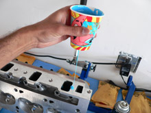
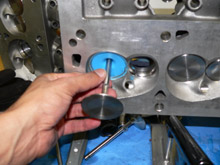
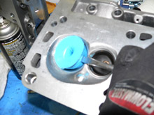
 The recommended pour procedure is to transfer the silicone
mix into a paper cup and then poke a small hole in the
bottom. Position the head so the port faces upward. Note
that the valve should be placed in the head (without spring.)
This will keep the silicone from running out.
The recommended pour procedure is to transfer the silicone
mix into a paper cup and then poke a small hole in the
bottom. Position the head so the port faces upward. Note
that the valve should be placed in the head (without spring.)
This will keep the silicone from running out.
|
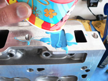
 The cup and hole method allows for the air bubbles introduced
by the mixing process to dissipate. The cup also gives
better control in ensuring the entire cavity is filled.
The cup and hole method allows for the air bubbles introduced
by the mixing process to dissipate. The cup also gives
better control in ensuring the entire cavity is filled. |
 Once the port is filled allow the silicone to cure for
6-8 hours. We prefer to let it sit overnight. Trying to
remove the mold prematurely can lead to tearing.
Once the port is filled allow the silicone to cure for
6-8 hours. We prefer to let it sit overnight. Trying to
remove the mold prematurely can lead to tearing.
|
 After the mold has cured we remove the valve and prepare
to extract the mold.
After the mold has cured we remove the valve and prepare
to extract the mold. |

 Using a screwdriver we carefully separate the mold from
the port walls. Don't be too concerned about gouging the
mold, be more cautious that the screwdriver doesn't nick
up the valve seats or guides.
Using a screwdriver we carefully separate the mold from
the port walls. Don't be too concerned about gouging the
mold, be more cautious that the screwdriver doesn't nick
up the valve seats or guides. |
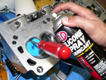
 We like to spray silicone lubricant into the port to help
release the mold. There are also release agents available
made just for this purpose however we find the silicone
spray works well.
We like to spray silicone lubricant into the port to help
release the mold. There are also release agents available
made just for this purpose however we find the silicone
spray works well.
|

 You can also spray through the guide plate boss to get
silicone lubricant thoroughly into the port.
You can also spray through the guide plate boss to get
silicone lubricant thoroughly into the port. |
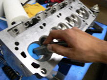
 If your valve guides protrude into the port you will most
likely need to use a blade and place a cut on the valve
head side of the mold. You only need to cut vertically
along half of the mold as shown, this will allow the mold
to move past the valve guide.
If your valve guides protrude into the port you will most
likely need to use a blade and place a cut on the valve
head side of the mold. You only need to cut vertically
along half of the mold as shown, this will allow the mold
to move past the valve guide. |
 Use a screwdriver to carefully pry the silicone mold out
of the port through the combustion chamber.
Use a screwdriver to carefully pry the silicone mold out
of the port through the combustion chamber. |

 The removal process takes a little patience and muscle.
You'll need to follow a sequence of prying, pulling, and
pushing from the port side. Spray silicone periodically
to lubricate the mold.
The removal process takes a little patience and muscle.
You'll need to follow a sequence of prying, pulling, and
pushing from the port side. Spray silicone periodically
to lubricate the mold. |

 Once you get enough of the mold out you can grab hold
and yank it out of the runner.
Once you get enough of the mold out you can grab hold
and yank it out of the runner. |
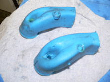
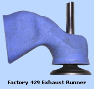
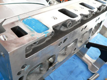
 The end result is precise 3D view of the inside of your
runner. As you can see it becomes very clear where the
restrictions are, and what areas need work. On both these
molds it is clear the pushrod passage pinches the port.
The end result is precise 3D view of the inside of your
runner. As you can see it becomes very clear where the
restrictions are, and what areas need work. On both these
molds it is clear the pushrod passage pinches the port.

|
|