3G Alternator - Installation
Installation of the 3G alternator can eb accomplished
with standard hand tools, however access to a Dremel
grinder or grinding wheel will be requried to peform
the bracket modification. Total time to upgrade
is less than 2 hours, and we do recommend the PA
Performance wiring kit and fuse to handle the high
current output.
|
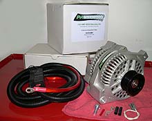
 We're installing PA Performance's
3G upgrade kit on our 5.0L Mustang Cobra. We also
opted for the 4-ga. power wire and 200 amp fuse
kit to ensure the high current doesn't burn up the
stock wiring.
We're installing PA Performance's
3G upgrade kit on our 5.0L Mustang Cobra. We also
opted for the 4-ga. power wire and 200 amp fuse
kit to ensure the high current doesn't burn up the
stock wiring. |

 Begin by disconnecting the
negative battery cable. Then remove the stock starter.
Begin by disconnecting the
negative battery cable. Then remove the stock starter.
|
| |
|
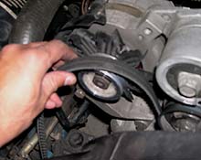
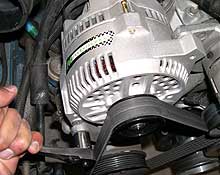
 Remove the serpentine belt
using an 18mm socket on the tensioner nut.
Remove the serpentine belt
using an 18mm socket on the tensioner nut. |
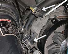
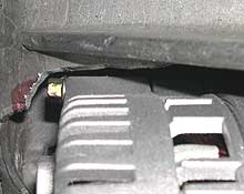
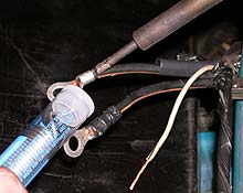
 Remove the regulator plug
(top arrow) and power output plug (lower) from the
alternator, gently prying with a screwdriver.
Remove the regulator plug
(top arrow) and power output plug (lower) from the
alternator, gently prying with a screwdriver. |
| |
|
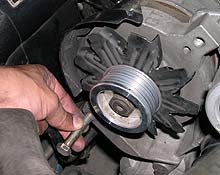
 Remove the upper 9/16" and lower 5/8"
alternator-to-bracket bolts.
Remove the upper 9/16" and lower 5/8"
alternator-to-bracket bolts. |
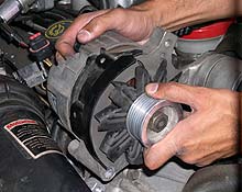
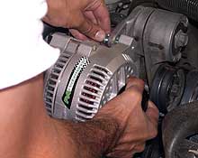
 The alternator can now be
removed from the bracket.
The alternator can now be
removed from the bracket. |
| |
|
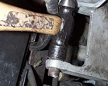
 With the stock alternator out of the way, tap the
bushing in the bracket forward to gain clearance
for the new alternator.
With the stock alternator out of the way, tap the
bushing in the bracket forward to gain clearance
for the new alternator. |
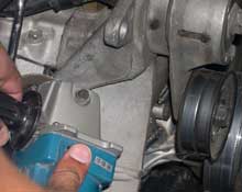
 The 3G alternator has a slightly larger housing
which requires clearancing the stock mounting bracket.
You can simply take a die grinder and hack out the
area shown, without removing the bracket from the
car. If you do this, be sure to keep the shavings
away from the new alternator.
The 3G alternator has a slightly larger housing
which requires clearancing the stock mounting bracket.
You can simply take a die grinder and hack out the
area shown, without removing the bracket from the
car. If you do this, be sure to keep the shavings
away from the new alternator. |
| |
|
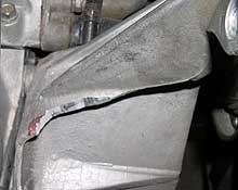
 The aluminum is easy as butter to grind away. This
image shows where and how much to remove.
The aluminum is easy as butter to grind away. This
image shows where and how much to remove. |
 Test fit the alternator in the bracket to confirm
adequate clearance.
Test fit the alternator in the bracket to confirm
adequate clearance. |
| |
|
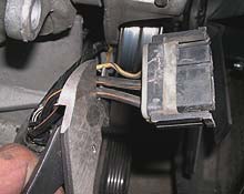
 Peel back the electrical tape on the power output
plug, and cut the three wires (two black/orange
and one yellow) 1/2" to 1" from the plug.
Peel back the electrical tape on the power output
plug, and cut the three wires (two black/orange
and one yellow) 1/2" to 1" from the plug. |
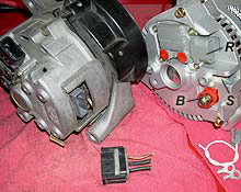
 The new 3G alternator (right) has slightly different
electrical connections than the stock 2G unit. The
power plug we cut in step 11 is no longer needed.
The stock regulator plug will connect right up to
the 3G socket (R). We'll attach ring terminals to
the two black with orange stripe wires from the
cut power plug will attach to the battery terminal
(B) . The yellow wire from the cut power plug will
connect to the stator terminal (S) using the white
lead and connector provided (lower right.)
The new 3G alternator (right) has slightly different
electrical connections than the stock 2G unit. The
power plug we cut in step 11 is no longer needed.
The stock regulator plug will connect right up to
the 3G socket (R). We'll attach ring terminals to
the two black with orange stripe wires from the
cut power plug will attach to the battery terminal
(B) . The yellow wire from the cut power plug will
connect to the stator terminal (S) using the white
lead and connector provided (lower right.) |
| |
|
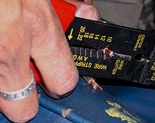
 Using wire strippers, remove about 1/4" insulation
on the ends of the three wires.
Using wire strippers, remove about 1/4" insulation
on the ends of the three wires. |
 Slip on the heat shrink tubing, and crimp and/or
solder the ring terminals to the two black/orange
stripe wires. Use the butt connector to crimp together
the white wire and the supplied stator plug.
Slip on the heat shrink tubing, and crimp and/or
solder the ring terminals to the two black/orange
stripe wires. Use the butt connector to crimp together
the white wire and the supplied stator plug.
|
| |
|
 Mount the alternator in
the bracket. Use the supplied upper mounting bolt
and the stock lower bolt. Leave them hand tight
until the wiring and belt is on.
Mount the alternator in
the bracket. Use the supplied upper mounting bolt
and the stock lower bolt. Leave them hand tight
until the wiring and belt is on.
|
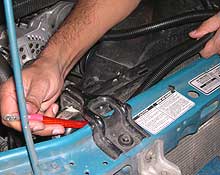
 The next step is to route
the 4-ga. power cable. The cleanest method is along
the radiator support as shown.
The next step is to route
the 4-ga. power cable. The cleanest method is along
the radiator support as shown.
|
| |
|

 Attach one end of the cable to the battery side
of the starter relay. The fuse
holder can be positioned flat against the side
of the battery.
Attach one end of the cable to the battery side
of the starter relay. The fuse
holder can be positioned flat against the side
of the battery.
|
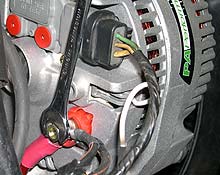
 Attach the regulator (top) and stator (white wire)
connectors to their respective sockets. The 4-ga.
power wire and two black/orange stripe wires all
attach to the battery terminal.
Attach the regulator (top) and stator (white wire)
connectors to their respective sockets. The 4-ga.
power wire and two black/orange stripe wires all
attach to the battery terminal. |
| |
|
 Install the serpentine belt
and then tighten up the lower and upper alternator
mounting bolts.
Install the serpentine belt
and then tighten up the lower and upper alternator
mounting bolts.
|
 The final step is to reconnect
the negative battery terminal, then check for proper
charging using a voltmeter. You should see over
12 volts at idle. Be sure to check our video
clips for a full output test.
The final step is to reconnect
the negative battery terminal, then check for proper
charging using a voltmeter. You should see over
12 volts at idle. Be sure to check our video
clips for a full output test. |
|
|
| |
|
|
|