Camshaft and valvetrain components directly determine how reliably an engine performs throughout its service life. Before choosing a camshaft and valvetrain, you must first understand how they work and how you want your engine to perform. Are you building a driver where low- and midrange torque are important or are you building a high revving racing engine that makes peak torque at high RPM?
Any camshaft manufacturer’s catalog lists dozens of camshaft types for the same type of engine. This chapter helps you sort through what each of the terms mean and how they affect your engine’s performance and durability.
Street Cams

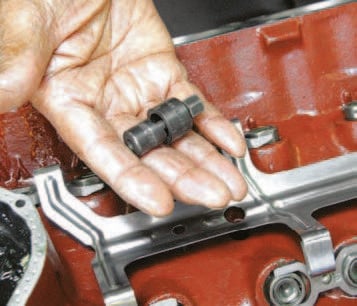
Getting into roller technology is expensive, but a great lifelong investment in what you gain in performance and huge frictional reduction. This is a small base circle roller cam designed to clear rod bolts in a stroker.
In my experience, the best street performance cams are ground with a lobe separation between 108 and 114 degrees. Keeping lobe separation above 112 degrees improves drivability because the engine idles smoother and makes better low-end torque. There’s also more vacuum at idle for accessories and power brakes. This is what you want from a street engine. Anytime lobe separation is below 108 degrees, idle quality and streetability suffer. But there’s more to it than just lobe separation. Compression and cam timing must be considered together because they always affect each other. Valve timing events directly affect cylinder pressure and ultimately working/dynamic compression. Long intake valve duration reduces cylinder pressure. Shorter intake duration increases cylinder pressure. Too much cylinder pressure can cause detonation (pinging). Too little and torque is lost. Cam manufacturers figure stock compression ratios into their camshaft selection tables, which makes choosing a camshaft easier than it’s ever been. Follow the cam manufacturer’s recommendations and you will be pleased with the result most of the time.
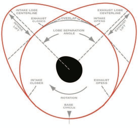
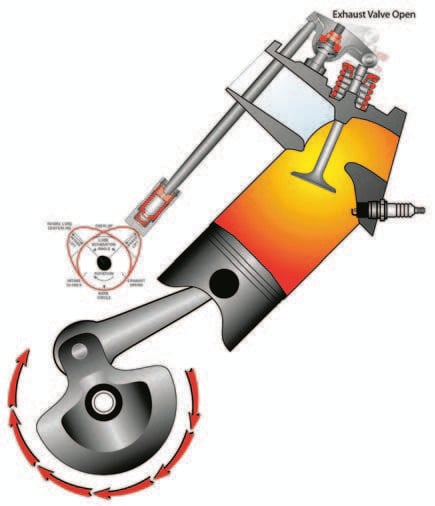
LEFT: This Comp Cams illustration shows the dynamics of what a camshaft does. This applies to Clevelands, as well as nearly all OHV V-8 engines. (Photo courtesy of Comp Cams) RIGHT: An engine’s “personality” comes from cam profile: lift, duration, lobe separation (lobe centers), valve overlap. (Photo courtesy of Comp Cams)


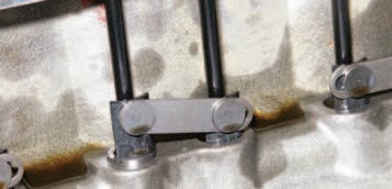
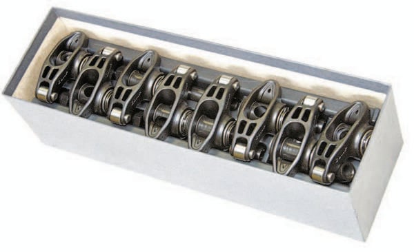
TOP LEFT: The spider-style, roller-tappet system is borrowed from Ford’s 5.0- and 5.8-liter roller-tappet V-8s that arrived in the mid 1980s. It is both affordable and effective consisting of the spider (retainer) assembly and dog bones (to keep tappets squared). TOP RIGHT: Flat-tappet technology is affordable, but presents long-term losses such as internal friction and profile limitations. Friction reducers include dual-roller timing sets and roller-tip stamped-steel rocker arms. BOTTOM LEFT: Linked roller tappets are expensive, but less troublesome than spider types with fewer parts. The beauty of a roller cam is how aggressive you can go and keep a civilized idle and cruise. BOTTOM RIGHT: Flat-tappet cams, though popular because they are affordable, have drawbacks. They’re limited in performance potential because you can’t go with the kind of aggressive ramp (valve opening and closing) you see with roller cams. They also wear significantly more than a roller cam which robs power. This means more internal friction and stolen power.

LEFT: You don’t have to drill the block for spider retaining bolts and mollies. This retrofit kit consisting of mollies and bolts enables you to lock the spider at oil drainback holes. RIGHT: A roller cam is a great internal friction reducer because it eliminates the drag of 16 tappets and lobes. Though this is more expensive, it is a great investment in engine life and performance. How much power is lost to friction? For every bit of friction lost, power is gained.

Lift and Compression
Be conservative with your cam specs if you want reliability and an engine that lives a long time. Choose a conservative lift profile (.500-inch lift). High-lift camshafts beat the daylights out of a valvetrain. And they put valve-to-piston clearances at risk. Watch duration and lobe separation closely, which help you be more effective in camshaft selection. Instead of opening the valve more (lift), you want to open it longer (duration) and in better efficiency with piston timing (overlap or lobe separation).
Always bear in mind your induction, heads, and exhaust. The savvy engine builder understands that in order to work effectively, an engine must have matched components. Cam, valvetrain, heads, intake manifold, and exhaust system must all work as a team or you’re just wasting time and money. If you’re going to use stock cylinder heads, your cam profile need not be too aggressive. Opt for a cam profile that gives you good low- to mid-range torque. Torque doesn’t do you any good on the street when it happens at 6,000 rpm. Choose a cam profile that makes good torque between 2,500 and 4,500 rpm. Otherwise, you’re just wasting engine.
One thing to remember with camshaft selection is how the cam works with your engine’s cylinder heads. Take a close look at valve lift with a particular cylinder head and determine its effect. Some camshafts actually lose power with a given head because there’s too much lift or duration. This is why you want to understand a cylinder head before choosing a camshaft. You want to seek optimum conditions with any cylinder head/camshaft combination. This means doing your homework before making a decision
What type of fuel do you intend to run in your engine? This also affects camshaft selection. You can actually raise compression if you’re running a mild camshaft profile or using a higher octane fuel. Camshaft timing events must be directly tied to compression ratio. The longer the duration, the lower cylinder pressure and working compression. The shorter the duration, the less air brought into the cylinder, which also affects compression.
Your objective needs to be the highest compression possible without detonation, which harms the engine. With this in mind, you want the most duration possible without compression extremes. Duration is what gives you torque, as long as compression is sufficient.
Valve Overlap
Valve overlap is the period between exhaust stroke and intake stroke when both valves are slightly off their seats. This occurs to improve exhaust scavenging and cylinder filling. It improves exhaust scavenging by allowing the incoming intake charge to push remaining exhaust gases out by the closing exhaust valve. With the exhaust valve completely closed, you wouldn’t get scavenging. The greater the overlap in a street engine, the less torque the engine makes down low where you need it most. This is why you want less valve overlap in a street engine and more in a racing engine, which makes its torque at high RPM. Increased valve overlap works best at high RPM. Street engines need 10 to 55 degrees of valve overlap to be effective torque powerhouses. When valve overlap starts traveling above 55 degrees, torque on the low end falters. A really hot street engine needs more than 55 degrees of valve overlap, but not much more. For example, racing engines need 70 to 115 degrees of valve overlap because that is what you need at high RPM
For a street engine, valve overlap should maximize torque, which means taking a conservative approach in the first place. Push overlap as far as you can without compromising torque. You also have to figure in lift and duration with valve overlap to see the complete power picture.
Lobe-Separation Angle
Lobe separation angle is another area of consideration in street cam selection. This camshaft dynamic is chosen based on displacement and how the engine will be used. Rule of thumb is this: Consider lobe separation based on how much displacement and valving you’re going to be using. The smaller the valves, the tighter (fewer degrees) the lobe separation should be. However, tighter lobe separation does adversely affect idle quality. This is why most camshaft manufacturers spec their cams with wider lobe separations than the custom grinders.
Duration
Duration in a street engine is likely the most important dynamic to consider in the selection process. Why increase duration whenever less lift is desired? Because your airflow gets into the cylinder bore two ways: lift and duration. You can open the valve more and for less time to get more airflow. Or you can open the valve less and keep it open longer via duration to get more airflow. Each has a different influence on performance. Duration is determined by the size of the cylinder head and amount of displacement, and how the engine will be used. Excessive duration hurts low-end torque, which is what you need on the street. So balance must be archived by maximizing duration without losing low-end torque. This is done by using the right heads with proper valve sizing. Large valves and ports don’t work well at all for street use. Mix in too much duration and you have a real slug at the traffic light.
So what does this tell you about duration? You want greater duration whenever displacement and valve sizing go up. Increasing duration falls directly in line with torque peak and RPM range. And this does not mean you necessarily gain any torque as RPM increases. It means your peak torque simply comes in at a higher RPM range. For example, if your engine is making 350 lb-ft of torque at 4,500 RPM and you increase duration, you may well be making that same amount of torque at 5,200 rpm. In short, increased duration does not always mean increased torque.
Compression has a direct effect on what duration should be. When you’re running greater compression, you have to watch duration closely because it can drive cylinder pressures too high. Sometimes you curb compression and run greater duration depending on how you want to make power. When you have greater duration, the engine makes more power on the high end and less on the low end. This is why you must carefully consider duration when ordering a camshaft. Higher compression with a shorter duration helps the engine make torque down low where you need it most in a street engine. The thing to watch for with compression is detonation and overheating. Maximum street compression is around 10.0:1.
Valve Lift
Think about valve lift as it pertains to an engine’s needs. Small-blocks generally need more valve lift than big-blocks. As you increase lift, you generally increase torque. This is especially important at low- and mid-RPM ranges, where it counts on the street. Low-end torque is harder to achieve with a small-block because these engines generally sport short strokes and large bores. Your objective needs to be more torque with less RPM if you want your engine to live longer. Revs are what drain the life out of an engine more quickly.
To make good, low-end torque with a small-block, you need a camshaft that offers a combination of effective lift and duration. As a rule, you want to run longer intake duration to make the most of valve lift. You get valve lift via the camshaft to be sure. But, rocker arm ratio is the other half of the equation. The most common rocker arm ratio is 1.6:1, which means the rocker arm gives the valve 1.6 times the lift as at the cam lobe. When you step up to a 1.7:1 ratio rocker arm, valve lift becomes 1.7 times, which you find at the lobe.
Camshaft Wear
It is best to spec a cam on the conservative side, especially if you’re building an engine for daily driving and weekend race use. Whenever you opt for an aggressive camshaft with a lot of lift, you’re putting more stress on the valve-stem, guide, and spring. The constant hammering of daily use with excessive lift is what kills engines without warning.
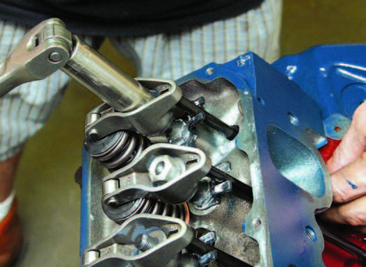
Taking this excessive wear logic a step further, it is vital that you ascertain proper centering of the rocker arm tip on the valve-stem tip when you’re doing valvetrain setup. This is performed by using the correct-length pushrod for your application. Use a pushrod checker to properly configure your Cleveland engine’s rocker-to-stem geometry.
A pushrod checker is little more than an adjustable pushrod used to determine rocker arm geometry. If the pushrod is too long, the tip is under centered on the valve-stem, causing excessive side loads toward the outside of the cylinder head. If the pushrod is too short, the rocker arm tip is over-centered, causing excessive side loading toward the inside of the head. In either case, side loads on the valve-stem and guide cause excessive wear and early failure. This is why you want the rocker arm tip to be properly centered on the valve-stem for smooth operation.
One accessory that reduces valve-stem tip wear and side loading is the roller-tip rocker arm. Roller-tip rocker arms roll smoothly across the valve-stem tip, virtually eliminating wear. Stamped-steel, roller-tip rocker arms are available at budget prices without the high cost of extruded or forged pieces.
Dual-Pattern Camshafts
A dual-pattern camshaft runs different profiles on the intake and exhaust side to meet individual need. You run dual-pattern profiles whenever you’re pushing up the revs. Typically, a dual-pattern camshaft runs a shorter exhaust-valve duration due to less time required to scavenge the exhaust gases at high RPM. It is also beneficial whenever you’re running nitrous or supercharging/turbocharging where exhaust scavenging is rapid and furious where you need more duration.
Another reason for running dual-patterns is Ford’s traditionally restrictive exhaust ports. Though the 351C-4V is blessed with generous intake port sizing, it is cursed with restrictive exhaust ports, which call for a dual-pattern cam profile. Intake needs to behave differently than exhaust. This is where you need more duration on the exhaust side in an effort to improve scavenging.
Race Cams
Building an engine for racing is different than building a street engine. Camshaft profile in a racing engine depends upon the type of racing you’re going to do, vehicle weight and type, even the type of transmission and rear axle ratio.
Drag racing mandates a different camshaft profile than road or circle track racing. A short-track racing engine needs to be able to produce huge amounts of torque in short order, for example. The same is true for a drag racer. These differences teach us something about engine breathing. Breathing effectiveness is determined by camshaft profile.
Lobe Separation
Lobe separation for the drag racing camshaft should be between 104 and 118 degrees, which is actually a broad range because drag racing needs can vary quite a bit. This is where you must custom dial in your application with a camshaft grinder. Most camshaft grinders have computation charts that show the right cam for a particular application. As your needs change, so must the camshaft profile.
If you’re going road racing, lobe separation becomes more specific, in the 106-degree range. Some cam grinders push lobe separation higher for the circle track engine, depending on conditions. Generally, the higher the lobe separation, the broader the torque curve (more torque over a broader RPM range).
Lifters
Four basic lifter (tappet) types are used in Clevelands: flat-tappet hydraulic and mechanical, and roller-tappet hydraulic and mechanical. Flat-tappet lifters were original equipment in all 335-series Cleveland engines. Roller tappets were increasingly used in Ford
factory V-8 engines after 1985, which is when aftermarket manufacturers began to make them available. More and more engine builds are witnessing the use of roller tappets because there’s less friction, smoother operation, and the ability to run a more aggressive profile without the drawbacks of a radical flat-tappet camshaft.
Roller tappets are more costly than flat tappets due to tighter tolerances and a greater number of parts. Their cost puts them outside of the budget-engine category, but they’re worth every penny in what they save in wear and tear. They also give you an advantage if you run a more aggressive camshaft profile.
Although hydraulic lifters saw more widespread use beginning in the 1960s, their use dates back to the 1920s. Hydraulic lifters don’t require periodic adjustment as do mechanical or solid lifters. As the camshaft and valve-train wear, hydraulic lifters expand with the wear via oil pressure to take up clearance. This keeps operation quiet and reliability sound.
Hydraulic lifters do well until cam lobe and valve-stem wear is so excessive the lifter can no longer take up the clearance. Then you hear the telltale “click” or tapping of rocker arm noise, especially when the engine is cold. Sometimes rocker arm click is a faulty lifter (leaking hydraulic pressure) or an excessively worn rocker arm. The first indication of an excessively worn rocker arm is the “clicking” that occurs at any engine temperature. It can also mean oil starvation at the rocker.
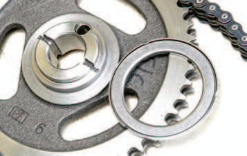
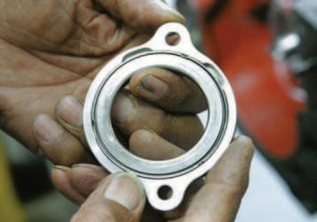

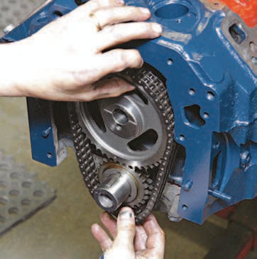
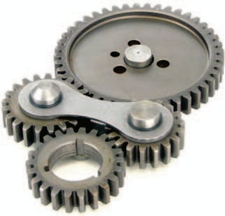
TOP LEFT: To find bonus power, you have to reduce friction everywhere it exists. This is a Torrington thrust bearing for small-block Fords including the Cleveland, which reduces internal friction at the camsprocket. TOP MIDDLE- The Torrington needle-bearing, cam sprocket thrust includes its own machined-steel cam plate for excellent wear and fit. Always check cam end play and sprocket to thrust clearances. TOP RIGHT: JGM Performance Engineering stresses the need to trim ragged edges from cam bearings to prevent journal scoring. Not all agree with this approach; however, it has worked very well for JGM. Cam journal scoring, no matter how slight, hurts oil pressure. BOTTOM LEFT: Friction reduction and cam timing accuracy are gained from the use of a dual roller timing set. It’s always important to save money; however, friction reduction is a great investment in engine life and efficiency. BOTTOM MIDDLE: Gear drives have been around for a long time and they deliver pinpoint valve timing accuracy; however, they’re expensive and can be noisy. This really is a personal choice depending on what you want your Cleveland to do. Gear drives are best left to racing because they are impractical for the street even though they sound cool. BOTTOM RIGHT: This is a two-piece Ford fuel pump eccentric for the 351C, which offers reduced internal friction.
Lifter and cam-lobe wear and failure are rarely caused by a manufacturing defect. They fail because you don’t give them a good start when it’s time to fire the engine in the first place. Flat-tappet camshafts must be broken in properly or failure is inevitable. Moly coat must be applied to the cam lobe and lifter face when you’re installing a flat-tappet camshaft. The engine must be operated at 2,500 rpm for 20 to 30 minutes after the initial fire-up to properly wear in the lobes. Synthetic engine oil should not be used until after the break-in period. During this period, check the pushrods for rotation.
Roller tappets don’t require break-in because rollers and cam lobes enjoy a good relationship to begin with.
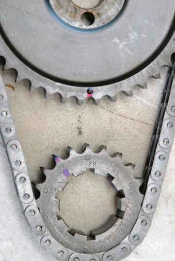

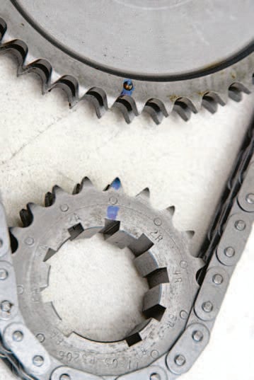
LEFT: Adjustable timing sprockets enable you to tune your Cleveland’s valve timing events. This is best done during engine buildup and degreeing, though it can be done in the car. MIDDLE: Advance the cam 2 degrees and gain torque depending upon how your cam compares with the cam spec card. Retard timing to gain horsepower. By the way, check valve to piston clearances as a precaution before buttoning up. RIGHT: Retard cam 2 degrees and gain horsepower but lose torque. Again, check those valve to piston clearances. The downside to adjustable cam sprockets at the crank is the limitation of 2-degree increments.
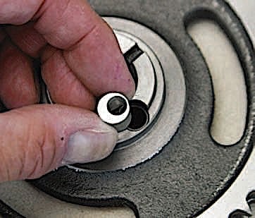
LEFT: Here’s another type of adjustable cam sprocket; small eccentrics are swapped in to advance or retard the cam sprocket. There are usually five eccentrics in the kit to fine-tune your valve timing. RIGHT: All engine builds should include degreeing the camshaft because you want to know exactly what you have right out of the box. Begin cam degreeing at zero at TDC and record valve timing events. When you advance valve timing, you gain low- to mid-range torque. When you retard valve timing, you gain horsepower on the high end. Make these adjustments in 2-degree increments and check valve-to-piston clearances.
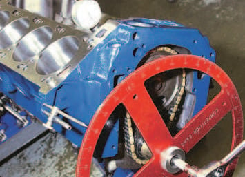
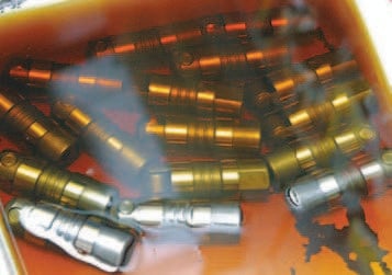
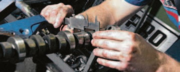
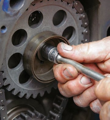
LEFT: JGM Performance Engineering uses a Comp Cams billet degree wheel, which is easy to see and use. You can turn the crank by the wheel or use a 1/2-inch-drive ratchet as shown. MIDDLE: Jim Grubbs of JGM Performance Engineering likes to soak lifters in hot oil with a moly additive to ensure deep-penetrating lubrication on start-up. RIGHT: Three-piece (left) versus one-piece (right) pushrod? Use a one-piece pushrod with .080-inch wall thickness even with a stock Cleveland because you want durability, and this is cheap life insurance.
The lobes are already hardened and the rollers provide a smooth ride. Flat-tappet mechanical camshafts are good for high-revving engines where the inaccuracies of hydraulic camshafts (lifter collapse) are unacceptable. Mechanical camshafts give you accuracy because there’s nothing left to chance. The lift moves with the cam lobe with solid precision. Given proper valve-lash adjustment, mechanical lifters do their job very well. The thing is, mechanical flat and roller tappets have to be adjusted periodically, which can be annoying on a daily driven street engine. This is where you need to do some soul searching before selecting a camshaft.
Valvetrain
At 6,000 rpm, valves slam against their seats 3,000 times per minute. Exhaust valves not only reciprocate vigorously at half the speed of the crankshaft, they’re subjected to combustion temperatures of approximately 1,800 to 2,000 degrees F. Lifters, pushrods, rocker arms, and valve-springs take a like amount of punishment without the levels of heat valves experience. Of all your engine’s components, valvetrain components are the most likely to fail. Many a broken valvespring or failed keeper has brought down the mightiest of engines. This is why your attention to this area is vital.
A valvetrain’s greatest ally is stability. Valvetrain systems must have matched components for stable operation. This is why camshaft manufacturers have increasingly gone to camshaft kits in recent years to help you choose the right combination of components. Camshaft companies make it easy to package your valvetrain system. Packaging a valve-train depends on how you want your engine to perform.
If you’re building a street engine that will be operating in the 2,500- to 5,500-rpm range, camshaft specifications need to have conservative torque because you want the engine to make good low-end torque for the street. Lifters, pushrods, rocker arms, and springs need to follow suit. Run a spring that is too soft for your camshaft profile and your engine experiences valve float (not enough spring pressure to close the valves quickly) at high RPM. Likewise, run a spring that’s too stiff and you can wipe the cam lobes from excessive pressure against the lobe. This is why running matched components is so important.
Proper valvetrain setup is about doing the math accurately because you don’t want to mess this up. Cam profi le and valvespring pressure must match. Too much spring pressure and you lose power and eat up the cam. Not enough spring pressure for the profile and you float valves at high RPM. You also want proper installed height void of coil bind.
Rocker Arms and Pushrods
The rocker arm and pushrod transfer the cam lobes energy to the valve stem. Think of the rocker arm as the camshaft’s messenger because the rocker arm multiplies lift, which makes the valve open farther than the camshafts lobe lift. Rocker arm types range from stock cast affairs all the way up to extruded and forged pieces with roller bearings and tips. Forged or extruded roller rocker arms are quite costly, which generally leaves them out of a budget engine program. However, this doesn’t mean you have to settle for stock cast or stamped-steel pieces either.
Stock cast or stamped-steel rocker arms don’t perform well under the heavy demands of radical camshaft profiles. An aggressive camshaft profile breaks a stock rocker arm. This is why it is always best to err toward heavy-duty whenever you’re building an engine. Stamped-steel, ball-stud, roller-tip rocker arms are a good first step toward valvetrain durability whenever
you opt for an aggressive camshaft. The roller tip reduces the stress you experience
with stock rocker arms. The thing is, when you increase lift and valve-spring pressure, a stamped-steel or cast roller-tip rocker arm doesn’t always stand up to the test, especially when spring pressures climb to more than 350 pounds. Even the best stamped-steel, roller-tip rocker arm will fail when overstressed.


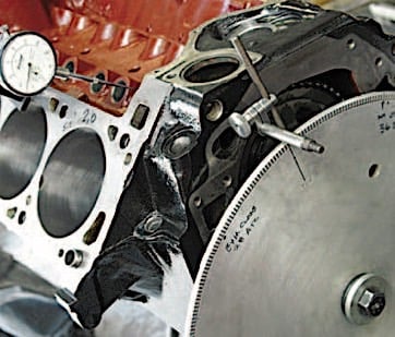
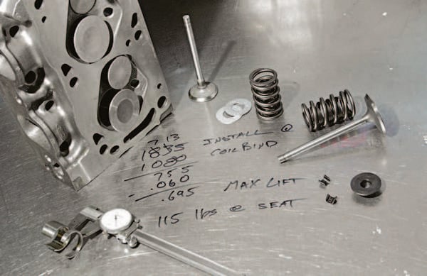
When degreeing a cam, don’t forget to temporarily bolt on the cylinder heads and do a mock-up to check valve to piston clearances. Some builders check just one bore while others check all of them. Unless clearances are dangerously close, you probably don’t need to check all eight bores. Minimum piston-to-valve clearance should be at least .060-inch. LEFT: Once valve-to-piston clearances are confirmed, check for coil bind at maximum lift. You want a minimum of .060-inch before you get into coil bind. You need more room, on the order of .100-inch. RIGHT: Valvespring pressure and cam profile must coincide with each other. The best advice I can offer is to go with the spring pressure your cam manufacturer specifies or to go with a complete kit with matched springs. Shown here is a mild spring with a dampener for stability and heat dissipation. This is a spring you would expect to see with a mild flat-tappet or roller cam.
When lift and spring pressures go skyward, you want a roller-pivot, roller-tip, forged rocker arm for your budget engine build. Going that extra mile with a super-durable rocker arm ensures longer engine life, especially if you’re going to drive it daily. For the weekend racer, stepping up to a better rocker arm is like writing a life insurance policy because marginal rocker arms do not stand up to the high-revving task. Roller-pivot, roller-tip rocker arms also ensure valvetrain precision and accuracy when the revs get high.
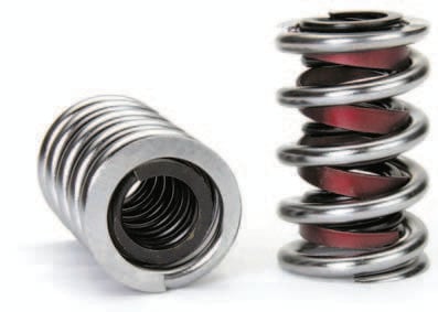
LEFT: More aggressive cam profiles call for greater spring pressures where you double or triple the number of springs. This is a Crane double spring with a damper. RIGHT: Blueprint every valvespring by removing ragged edges for buttery smoothness, then give them an anti-friction coating and generous amounts of engine assembly lube. This ensures a good start-up without scoring.
When it comes to valvetrain adjustment, Clevelands have flexibility in adjustable aftermarket studs where adjustable studs were not originally used. Early small-block Fords (1962–1967) had adjustable, ball/stud-mounted rocker arms. From 1968 to 1977, they received no-adjust, positive-stop rocker arm studs which are undesirable for the performance buff. From 1978 to present, the rocker arm stud was replaced with a new design, stamped-steel rocker arm, fulcrum, and bolt that mount atop a boss. Clevelands differ from other small-block Fords in that they never had a stud mounted rocker on common examples. Only the Boss 351 and 351 High Output had stud-mounted adjustable rockers.
The 335-series small-block engine family (351C, 351M, 400M) had two types of rocker arm arrangements from the factory. The Boss 351 (1971) and 351 High Output (1972) had adjustable, stud-mounted rocker arms. The rest had bolt-fulcrum style, no-adjust, stamped steel rocker arms as found on small-block Fords 1978-up.
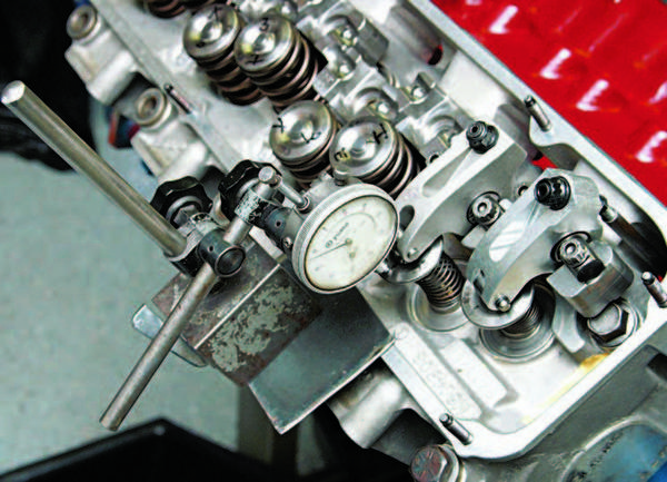
This is a good mock-up where valve-to-piston clearances and true valve lift are checked using a dial indicator.

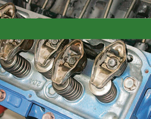
LEFT: Friction and wear reduction begin with a roller-tip rocker such as from Comp Cams, which has a 1.52:1 ratio. If you’re on a limited budget, this is a good rocker. The key to durability is to get your rocker arm geometry just right. You want the roller-tip to be dead-center on the valve stem with the valve fully open. RIGHT: Clevelands were originally fitted with two types of rocker arm packages. Most had this bolt-fulcrum, stamped-steel rocker arm package, which is not adjustable. The bolt-on fulcrum rocker arm first saw use on the 385-series 429/460. A 1971 Boss 351 or 1972 High Output has screw-in studs and adjustable rocker arms with guide plates.
Valve-Lash Adjustment
If you’re building a Cleveland with a bolt-fulcrum rocker, there is no valve lash adjustment. However, bolt-fulcrum rocker arms sometimes require pushrods of varying lengths to get into proper adjustment. If you have a noisy rocker arm, confirm lifter status before doing anything else. A collapsed lifter causes excessive rocker arm noise. According to Ford you are allowed 5 to 55 seconds of lifter leak-down time. A damaged or excessively worn rocker arm can make noise, as does a loose fulcrum-retaining bolt. Ford suggests a .060-inch-longer pushrod to help take up excessive clearance.
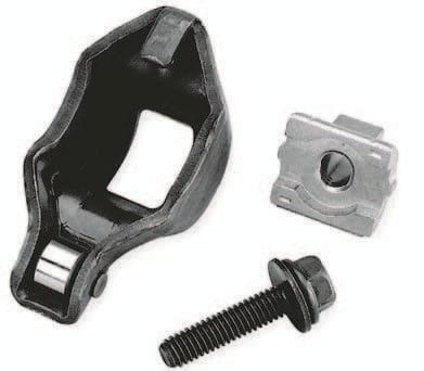
LEFT: Here’s the bolt-fulcrum rocker setup with roller tip from Crane. You want a steel fulcrum regardless of how you intend to build your no-adjust valve-train. RIGHT: The Ultra Pro Magnum rocker from Comp Cams for Cleveland is available in 1.73:1 and 1.80:1 ratios. These high-performance roller rockers come with one piece pushrods with .080-inch wall thickness and poly-locks.
Many go with an adjustable stud mounted rocker arm with mechanical or hydraulic tappets. There’s endless discussion about how to adjust valve lash on hydraulic-lifter Clevelands. However, adjustment is nothing more than common sense. Hydraulic-lifter pistons have a very limited amount of travel or preload: .020 to .060 inch. On top, that means approximately 1/4- to 3/4-turn at the rocker arm. When adjusting valve lash, you want the lifters smack on the cam lobes’ heels (valves closed) on compression stroke. But honestly, cam manufacturers offer even more precise advice: Slowly turn the crank until each valve closes completely, then, make your adjustment.
Turn the pushrod with your fingertips while tightening the rocker arm adjustment nut. When the pushrod becomes ever so slightly resistant to your fingertips, turn the adjustment nut 1/4 to 1/2 turn. Though Ford suggests 3/4-turn with some applications, this is too much. If you’re running poly locks, tighten the Allen screw lock. Do this in the engine’s firing order, one cylinder at a time.
You don’t know if you are successful until you fire the engine and it is at operating temperature. If there’s significant rocker arm noise, there’s too much lash and you need to go a little tighter. Some aftermarket rocker arms, such as the Comp Cams Pro Magnum or Ultra Pro Magnum, make a soft clicking sound, which makes a Cleveland sound more like it has mechanical tappets, but is of no consequence.
With roller or flat mechanical tappets, valve-lash adjustment is simple. As with hydraulic tappets, follow the firing order with both valves just closed. Valve lash between rocker arm tip and valve-stem is .022-inch cold for both intake and exhaust. When you start the engine, you should hear uniform rocker arm chatter. Any loud clicking is excessive valve lash.
Proper valve adjustment is crucial to both performance and durability. A valve that doesn’t seat from over-tightening ultimately burns and fails, not to mention misfires and rough operation.
Valves need contact with the seat not only for the obvious (compression) but also for heat transfer to the seat and water jacket. The .022-inch the rocker arm has at the valvestem give you the necessary allowance for safe operation.
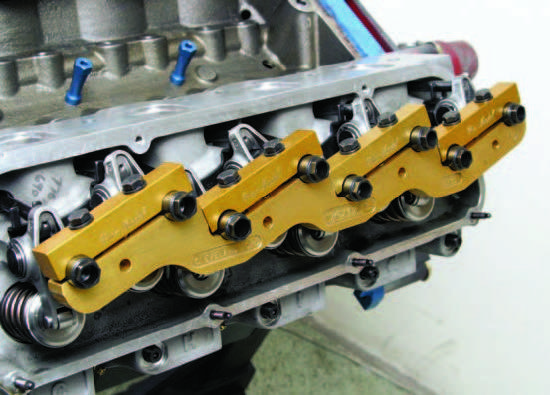
This rocker arm stud girdle (PN 1135) by Jomar is available from MPG Head Service. Stud girdles provide extraordinary valvetrain stability by securing all studs and limiting movement.
Pushrod Length
Proper pushrod length is a serious consideration for any engine builder. It can mean the difference between long engine life and having to pull heads in a few thousand miles. A pushrod that’s too long pushes the rocker arm tip under center, causing excessive side loading to the valvestem and guide. Likewise, a pushrod that’s too short does the same thing on the opposite side. A pushrod checker (found at your favorite speed shop) helps you make the right decision for not much money.
When checking pushrod length, the rocker arm tip should be close to center on the valvestem tip and dead-center with the valve fully open. Remember, the rocker arm tip is going to walk across the valve-stem tip when you come up on the high side of the cam lobe.
Take a black felt-tip marker and darken the valvestem tip. Then install the rocker arm and pushrod. Hand crank the engine and watch the valve pass through one full opening and closing. Get down along side the rocker arm and valvespring and watch the rocker arm travel. Then inspect the black marking for a wear pattern. This shows you exactly where the rocker arm tip has traveled across the valvestem tip.
The pattern should be centered on the valvestem tip. If it runs too much toward the outside of the valvestem tip, the pushrod is too short. If it runs toward the inside of the valvestem tip, the pushrod is too long.
Valve-lash adjustment begins at cylinder number-1 with both valves just closed. Twirl the pushrod with your fingertips while slowly tightening the rocker adjustment until there is slight resistance. Slowly tighten the adjustment clockwise 1/4- to 1/2-turn. Lock the adjustment down.
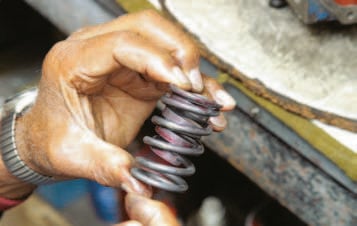
Valves and Springs
Valves and springs play an important role in power and reliability. Weak spots in either area can rob you of power or lead to engine failure. This is why choosing the right valves and springs is so important. Most cam manufacturers offer a variety of valvespring combinations designed to work well with the camshaft you have chosen. In fact the best way to shop for and buy a cam is to purchase a camshaft kit, which includes valve-springs, retainers, and keepers matched to your camshaft profile. You match a cam and springs because you want a compatible spring for the profile. More radical cams call for stiffer springs. Milder camshaft grinds need less valvespring pressure. Too much spring pressure can wipe the cam lobes. Too little can cause valve float (valve seating doesn’t keep up with the revs) at high revs.
Choosing the right valvespring is strictly a matter of following a camshaft grinder’s recommendations. Most springs are applicable to hydraulic or mechanical lifters. Some are specific only to roller camshafts. Crane Cams, for example, offers dozens of different valvespring types.
When you opt for a camshaft kit, there’s comfort in knowing the manufacturer has matched the springs to the camshaft profile. Most of the homework has been done for you. There won’t be concern about coil binding, or too much or too little spring pressure.
The best time to check for coil bind is when you’re degreeing the camshaft. Do this before permanently bolting on the heads. Most cam grinders tell you the recommended installed spring height and seat pressure. Correct installed height and spring pressure are achieved with the use of shims as necessary. Coil bind is checked by measuring coil spacing with the valve at maximum lift. There should be no less than .060 inch between the coils at full valve lift. Retainer to valve guide clearance at full lift is the same; no less than .060 inch. This clearance is vital because coil bind or retainer contact with the head causes valve-train failure. The .060 inch you give it allows for thermal expansion of metal parts and any camshaft aggressiveness and spring movement at high revs.
Another consideration is piston-to-valve clearance whenever you’re installing a camshaft with greater lift and duration. The most common practice is to press modeling clay into the piston valve reliefs, then temporarily install the head and valvetrain, then turn the crank two complete revolutions. If you feel any resistance, back off and remove the head. Chances are at this point you have valve to- piston contact. Forcing the crank bends the valve and/or damages the piston. If no resistance is felt in two full turns of the crankshaft, remove the head and examine the clay. Slice the clay at the valve relief and check the thickness of the clay. This is your valve to piston clearance, which should be no less than .060-inch.

Want to learn more? This content is sourced from CarTech’s book, Ford 351 Cleveland Engines: How To Build For Max Performance. You can learn more about this book here and use promo code “FORD” to save 40 percent off your order!