Allow me to reintroduce our newest project vehicle here at Ford Muscle! You might be familiar with the project we’ve been actively progressing on named Project F Word. We love our wild little 1969 F-100, and now we have a counterpart for the old girl, and its name is Project Red Storm. The 2018 F-150 4X4 single cab is the perfect base for a really badass project vehicle, especially given its 5.0-liter Coyote powerplant.
The F-150 is about to go under the knife and be transformed with help from some of the best names in the business including Whipple, Eaton, Moser, Stifflers, AmericanTrucks, and more, and we’re so happy you’re along for the ride.
We gave you a quick rundown on the direction the project would be headed back in June when we introduced a portion of its Maxtrac suspension system, but now it’s time to start making real power.
As we mentioned before, our friends at Whipple have been super supportive of Project Red Storm. The supercharger was installed in-house at Whipple headquarters in Fresno, California, and seeing as our truck is a California native, it was of utmost importance that the supercharger we chose was CARB-legal. We went with Whipple’s F-150 Gen V Stage 2 supercharger kit.
The Supercharger
The truck’s owner, Dave Lukason, knew he wanted to go with Whipple from the very beginning. “We decided to go with the Whipple Supercharger based on its stellar reputation for reliability and performance,” Dave explained.
With that in mind, we contacted our friends at Whipple Superchargers to decide on the best supercharger for the F-150 and decided on the 3.0L Gen V Stage 2 kit. The installation was done in the early stages of the COVID-19 pandemic, and thus, Whipple was still developing a prototype for the truck. (FYI: the production version is now available for purchase.)

“This was a prototype for the F-150 — the first one,” explained Whipple Superchargers’ Dustin Whipple. “We didn’t have a production calibration for the new kit, so we used our previous production, made necessary changes, and the results were amazing.”
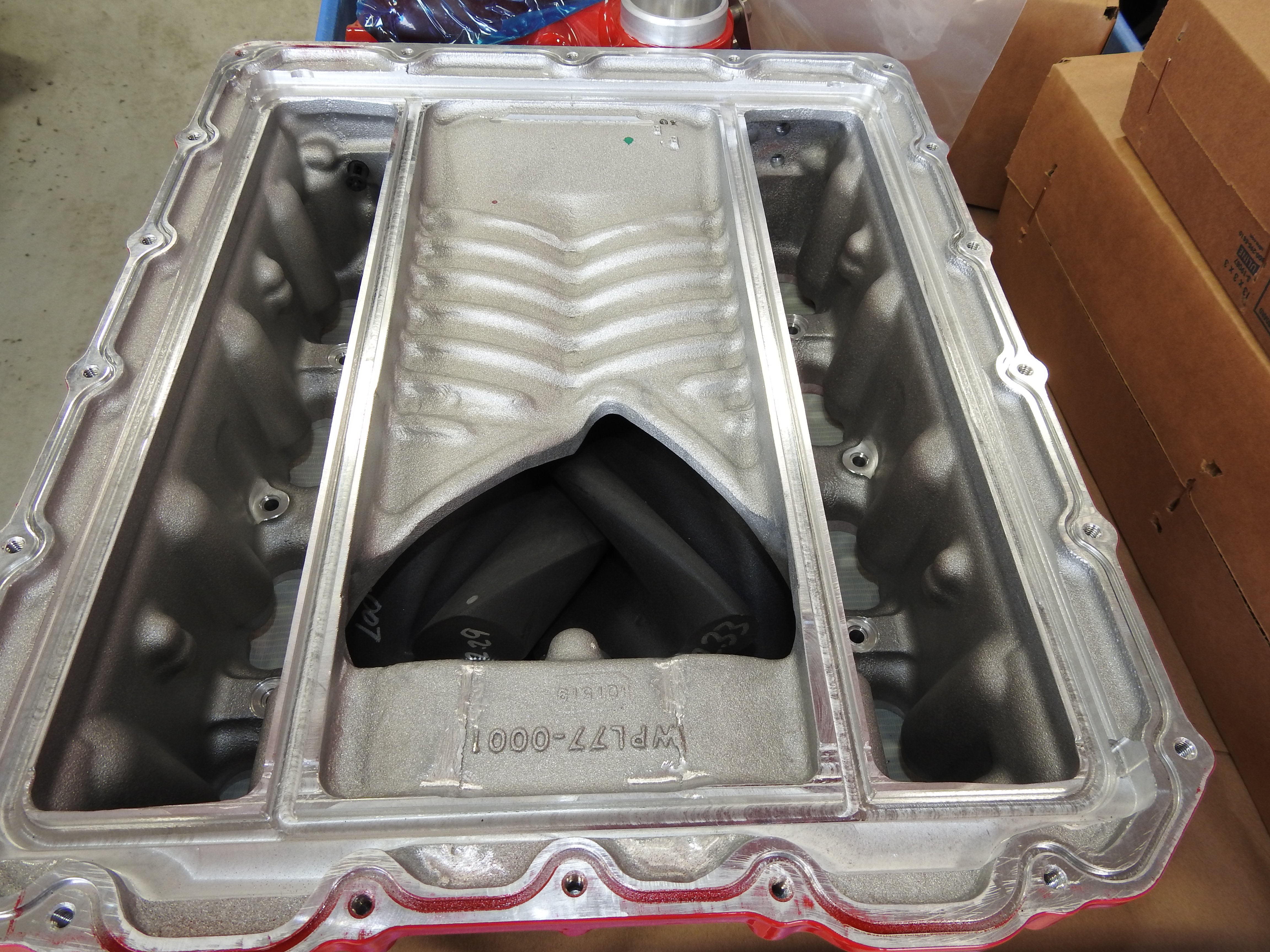
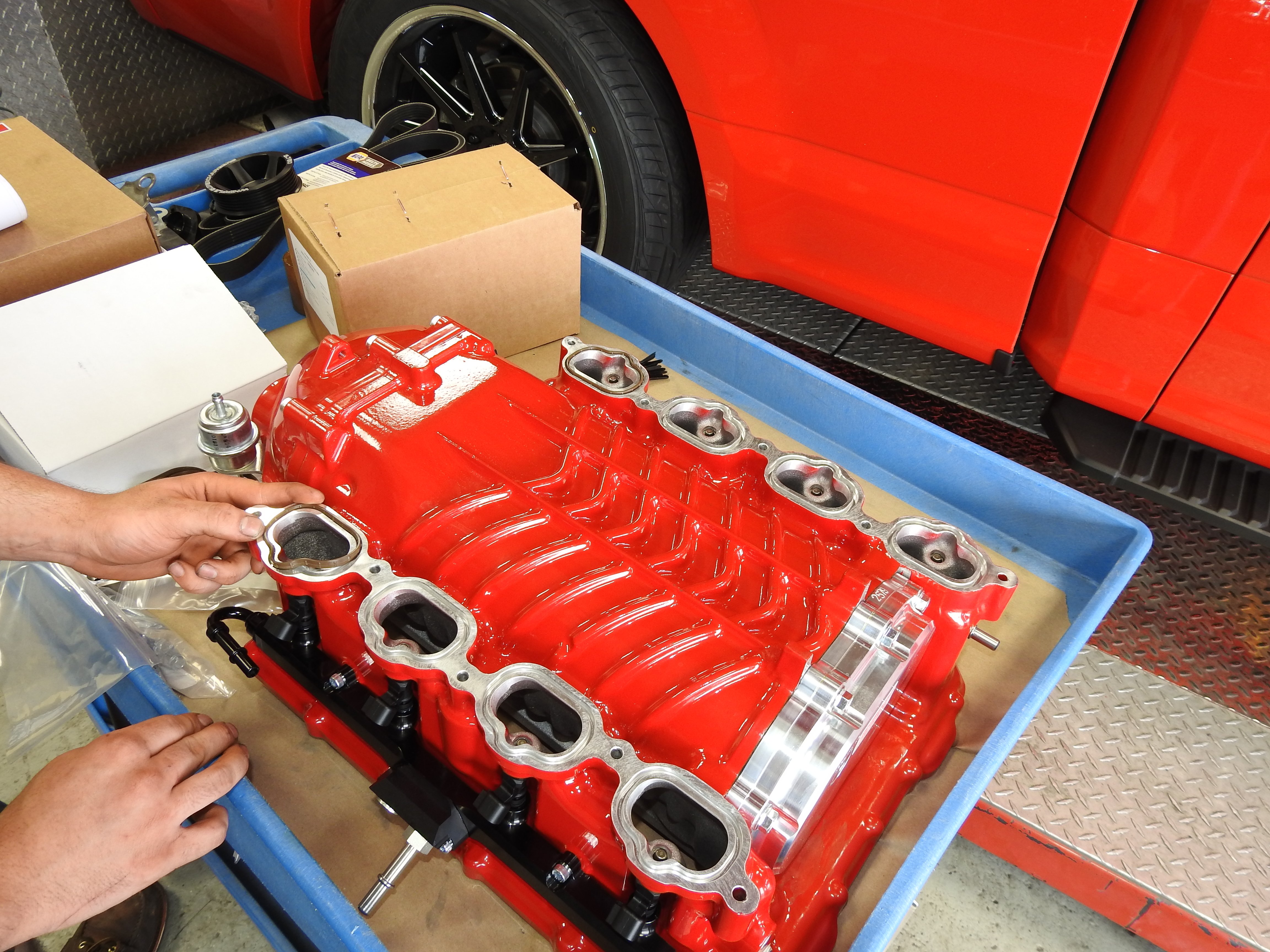
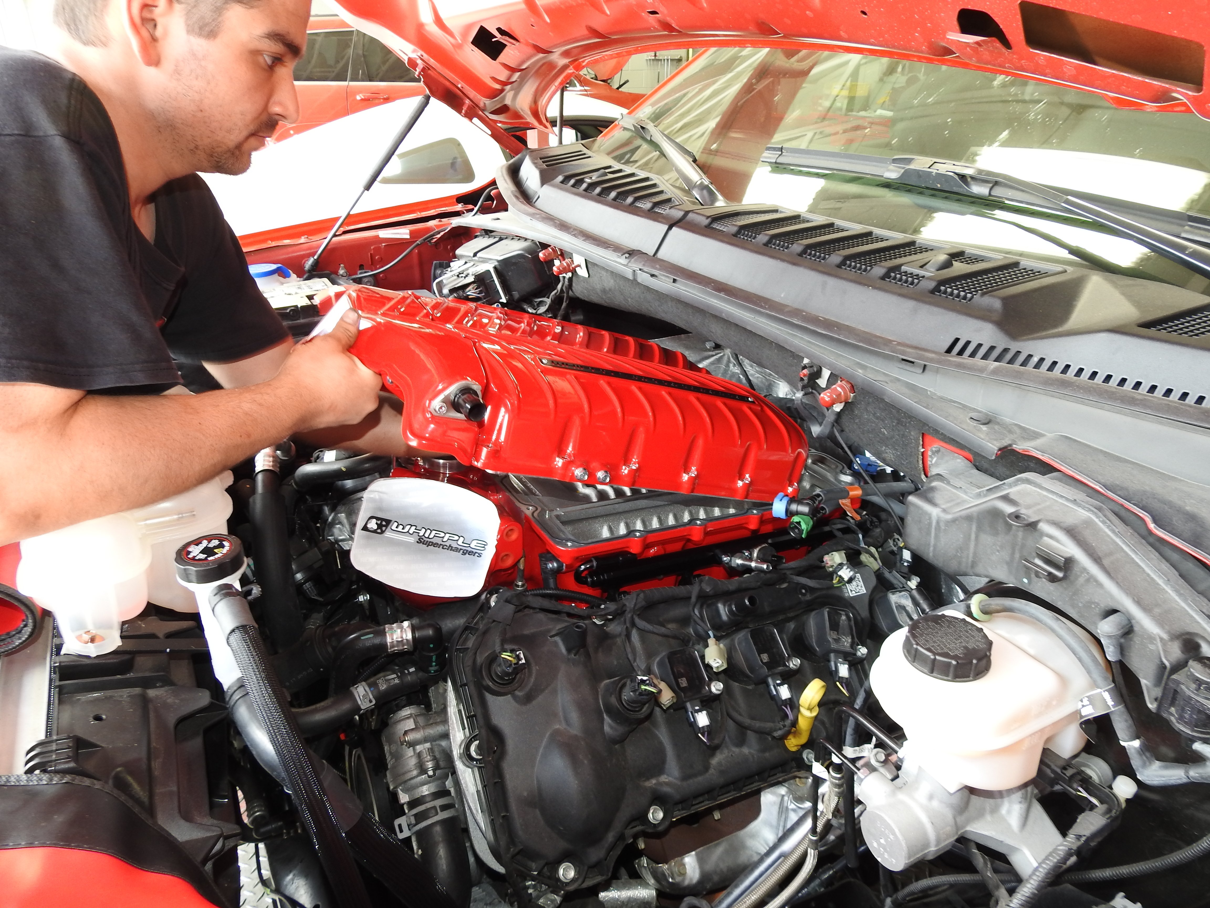
The 3.0-liter twin-screw supercharger with a huge 150mm front feed inlet was chosen for the completely stock engine, boosting power to the moon! But we’re getting ahead of ourselves here. What separates the Stage 2 from the Stage 1 is the addition of a unique “Roval” 132mm billet throttle body pre-set with factory electronics. The throttle body that Ford equipped our F-150 with was a mere 80mm. On any positive displacement blower, the throttle body can be real restriction – especially with a blower capable of moving this much air.
Whipple told us that this supercharger can produce up to 685 lb-ft of torque and 775 horsepower to the flywheel. It features a 3×4 rotor combination with improved sealing, as well as higher efficiency and more power production than Whipple’s previous generations.
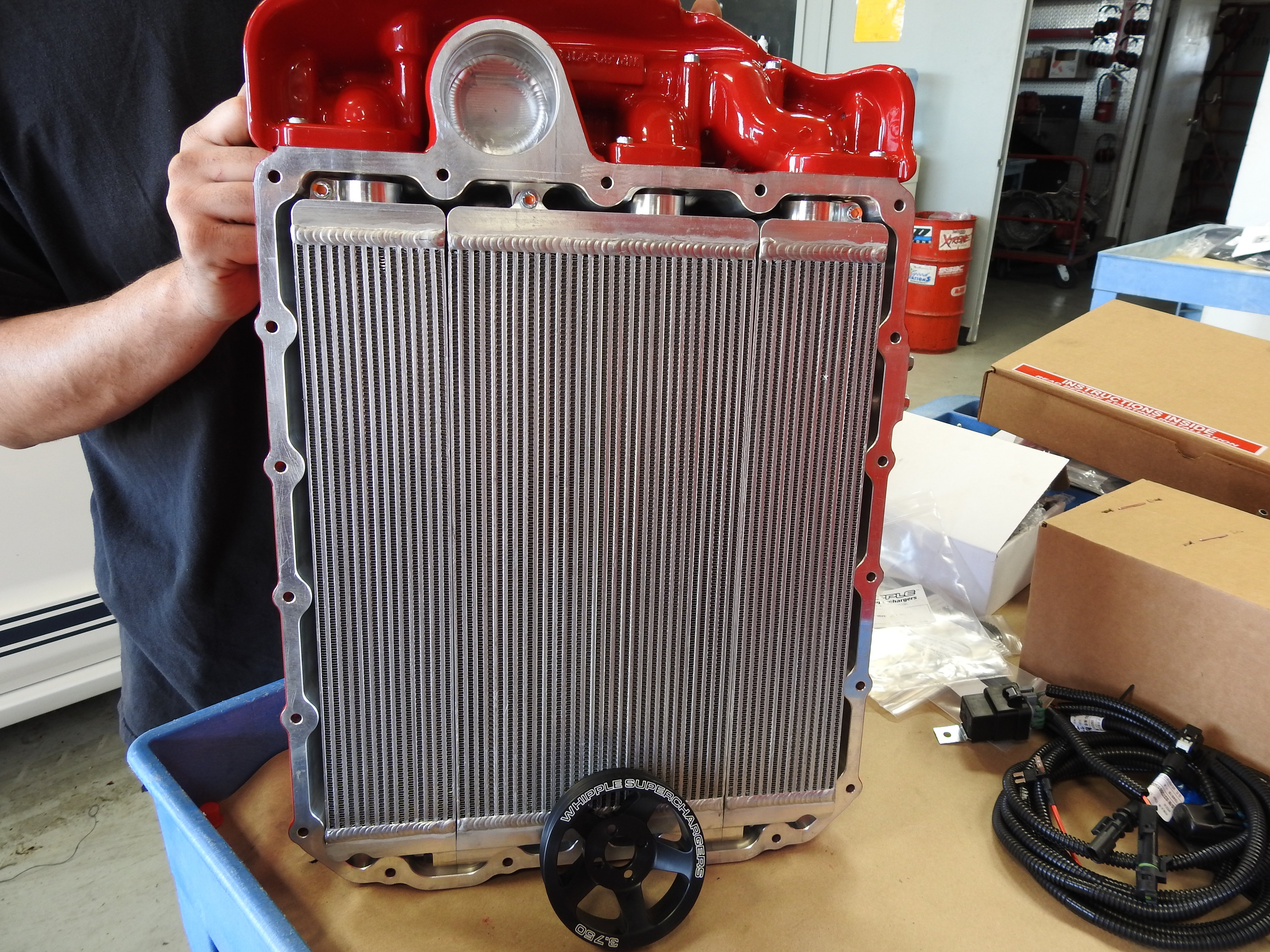
The inverted supercharger is designed to fit into the valley of the Coyote’s block, just above the direct injection system, thanks to its “upside down” integrated design. This design allows for Whipple to include the industry’s largest air-to-water intercooler in the kit to decrease temperatures and minimize pressure drop. The intercooler is nearly 55% larger than competitive variations, and allows for cooler, denser air leading to more (and safer) power. An included high-flow intercooler pump offers double the flow of typical, standard units. An oversized heat exchanger offers nearly 150% more volume than competitive products, and Whipple also equips this kit with an oversized aluminum intercooler reservoir which mounts behind the bumper. It offers the intercooler system over three gallons of capacity for cooler air temperatures, less heat soak, and more power.

And back to that calibration — Whipple has worked super hard to develop supercharger software that reconfigures things like fuel, spark, knock detection, torque management, transmission control, and electronic throttle control. The vehicle’s PCM keeps the engine in its perfect parameters through consistent monitoring of torque output and other details. If something slips, Whipple’s calibration will automatically reduce boost and torque output so as not to do damage. A 3-bar MAP sensor measures manifold pressure under boost, and an air temperature sensor properly sparks advance at a variety of RPM points. Meanwhile, the F-150’s 10-speed transmission is recalibrated to keep the engine in its peak torque range at nearly all RPM points while still allowing for off-road, tow, eco, and sport modes.
Included in the box is the supercharger itself, intercooler, oversized Crusher air system, and PCM programming via the new Whipple flash tool called Tomahawk, which also allows the user to read and erase codes and customize wheel and axle sizes. Whipple also includes Bosch MU52 55 lb-hr fuel injectors (replacing the stock 17 lb-hr port injectors), all parts and hardware required for installation, and in-depth step-by-step installation instructions.
And did we mention that when installed on a 2018-2020 F-150, this supercharger is 100% SMOG legal? This system can safely and legally be used in all 50 states!
“Through testing, Whipple obtains an Executive Order (EO) from the California Air Resource Board (CARB) stating the addition of the supercharger maintains emissions compliance to their standard, which is the most stringent,” explains Whipple product line director Nick Purciello. “With the increasing number of states adopting CARB standards, it is more important now than ever that we obtain this certification. Customers then have the piece of mind knowing their supercharged vehicle can be bought and sold legally across the country and not have to worry when it comes time for inspection and registration.”
The Installation
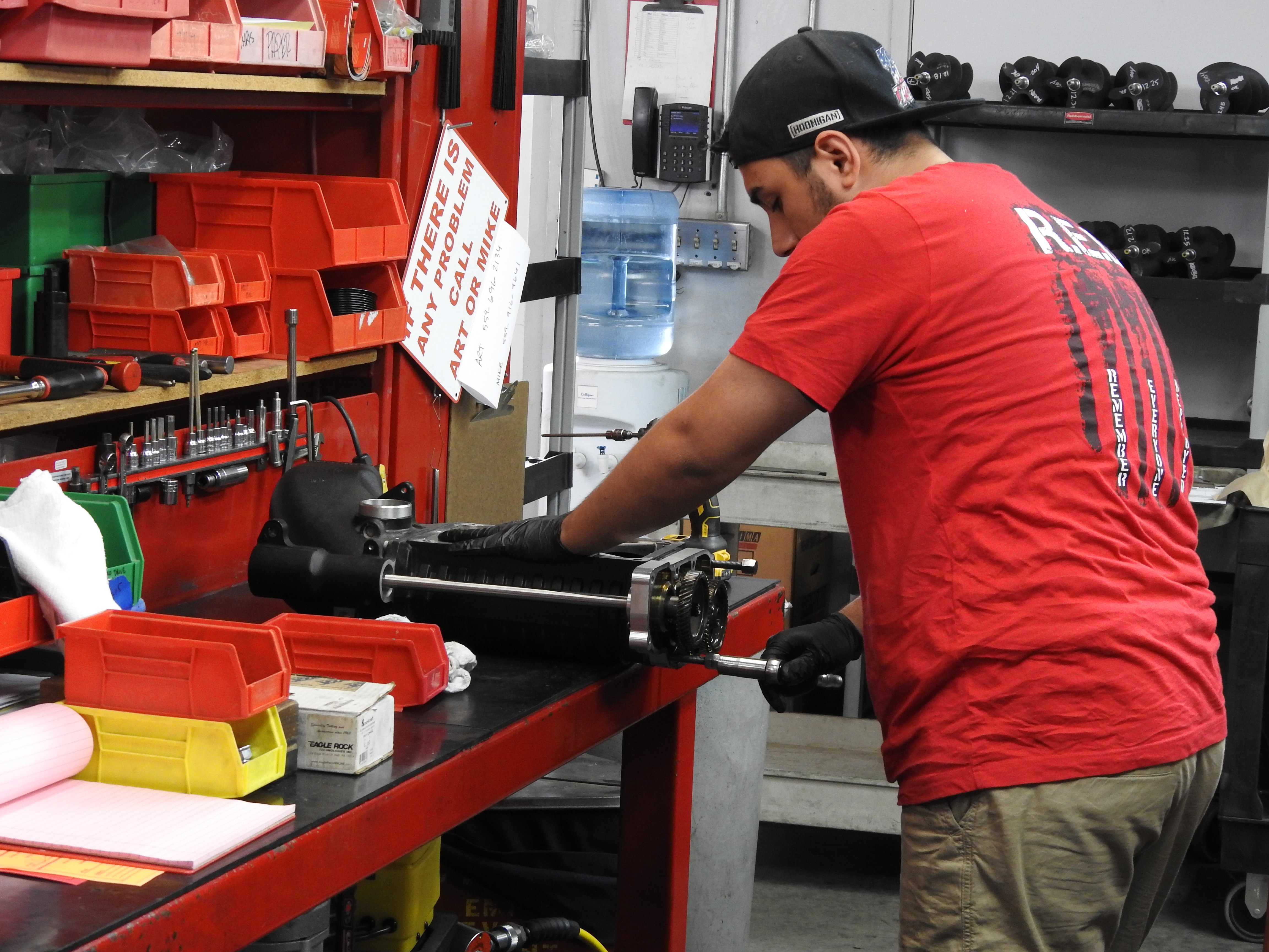
The installation process is intricate, so we turned to the experts for this part. As we said before, Project Red Storm was delivered to Whipple headquarters where she underwent a baseline dyno pull before going under the knife — but more on that later. We won’t bore you with all of the nitty gritty details of the installation, but here is a basic overview of what you can expect should you choose this supercharger for your truck. The aforementioned included installation instructions will break this down into an easy-to-digest process for you when you’re ready to get rolling.
It should be noted that our truck’s Coyote was 100% stock prior to the installation, and yours can be too. This supercharger was specifically designed for this type of application, with no additional modifications required for big power right out of the box. It will fit under the factory hood, the engine block does not need to be cut or ground, and no other interior modifications are required. Whipple has also equipped the kit with plug-and-play wiring with male and female connections for ease of installation.
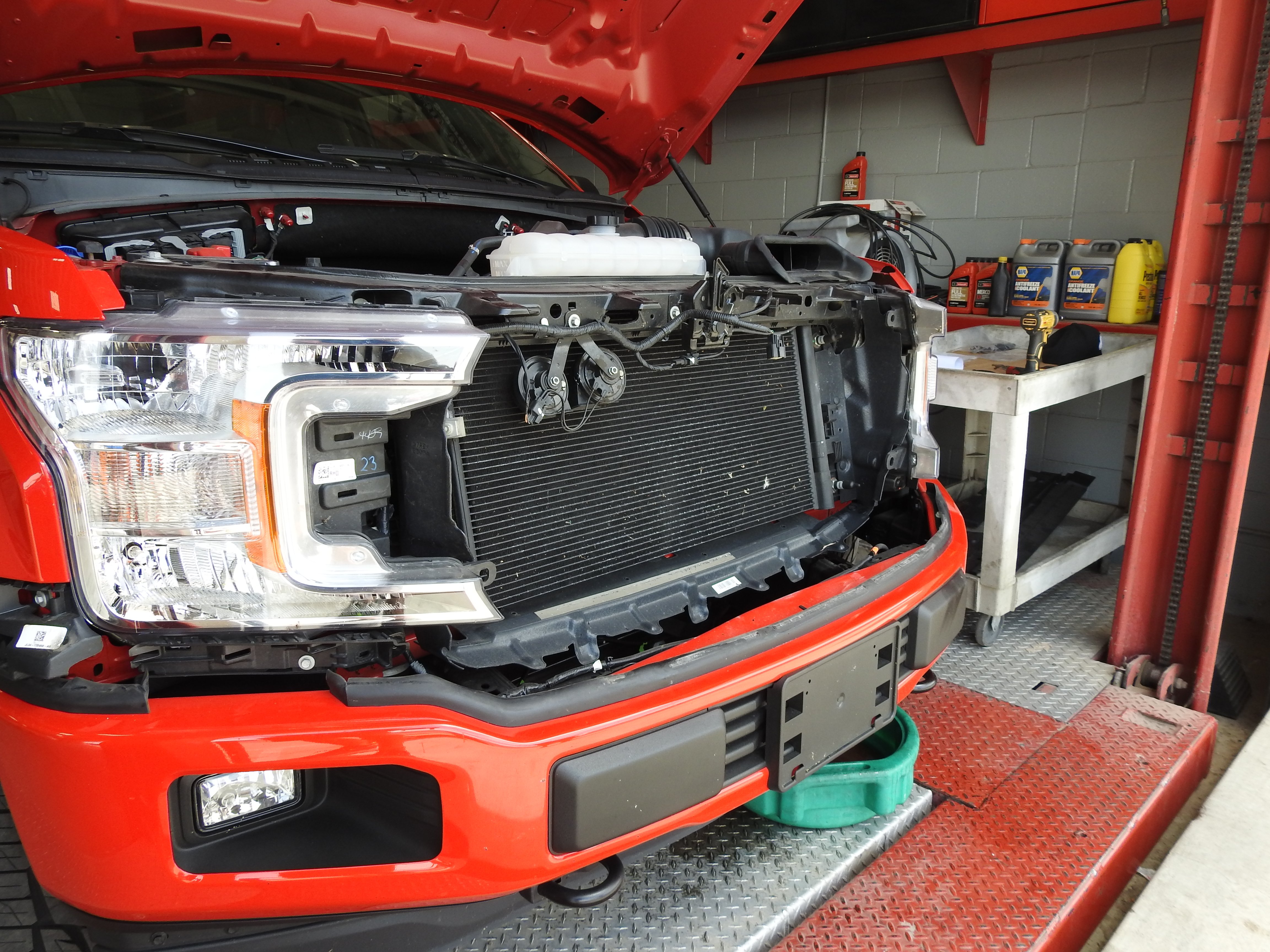
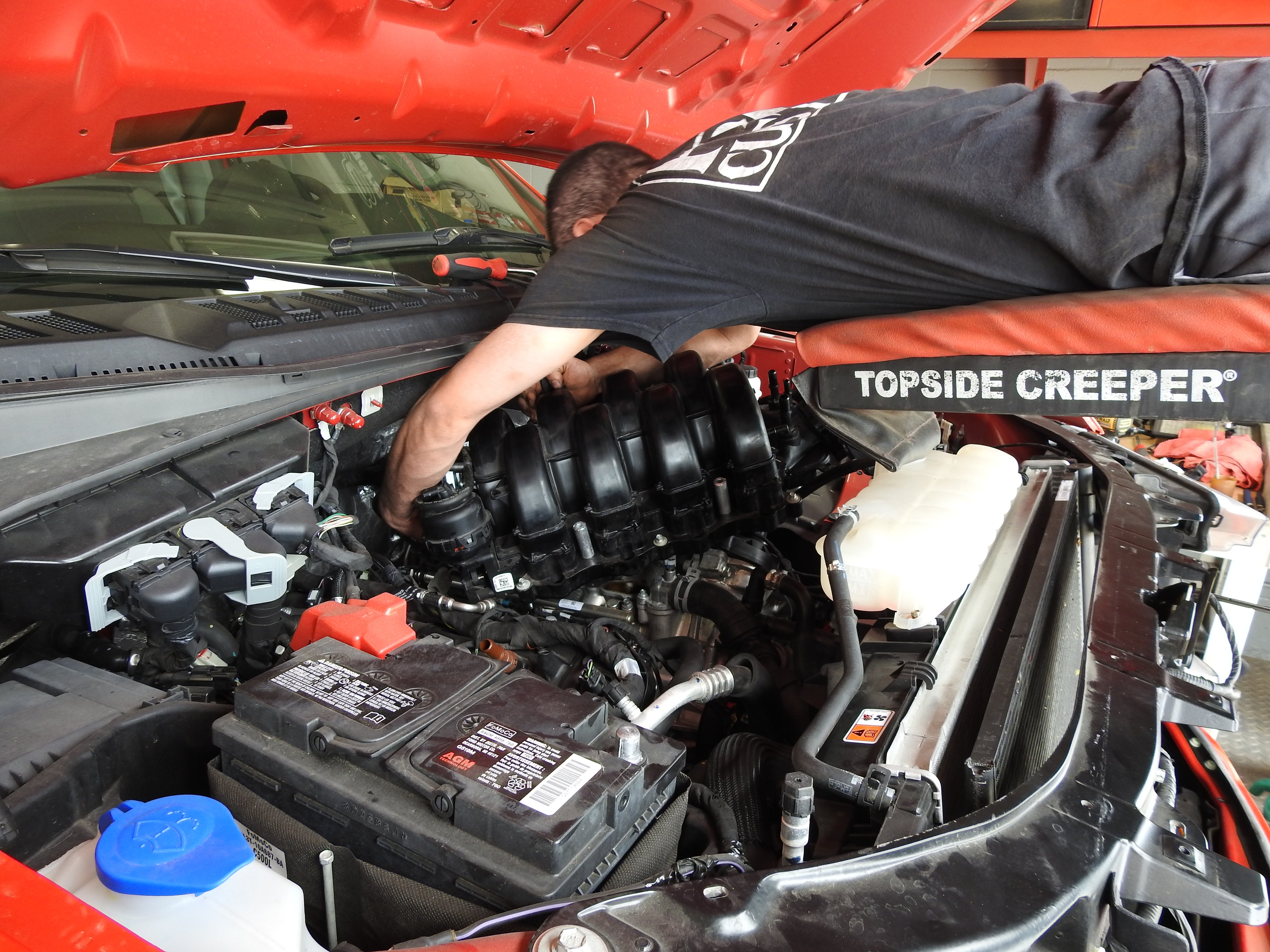
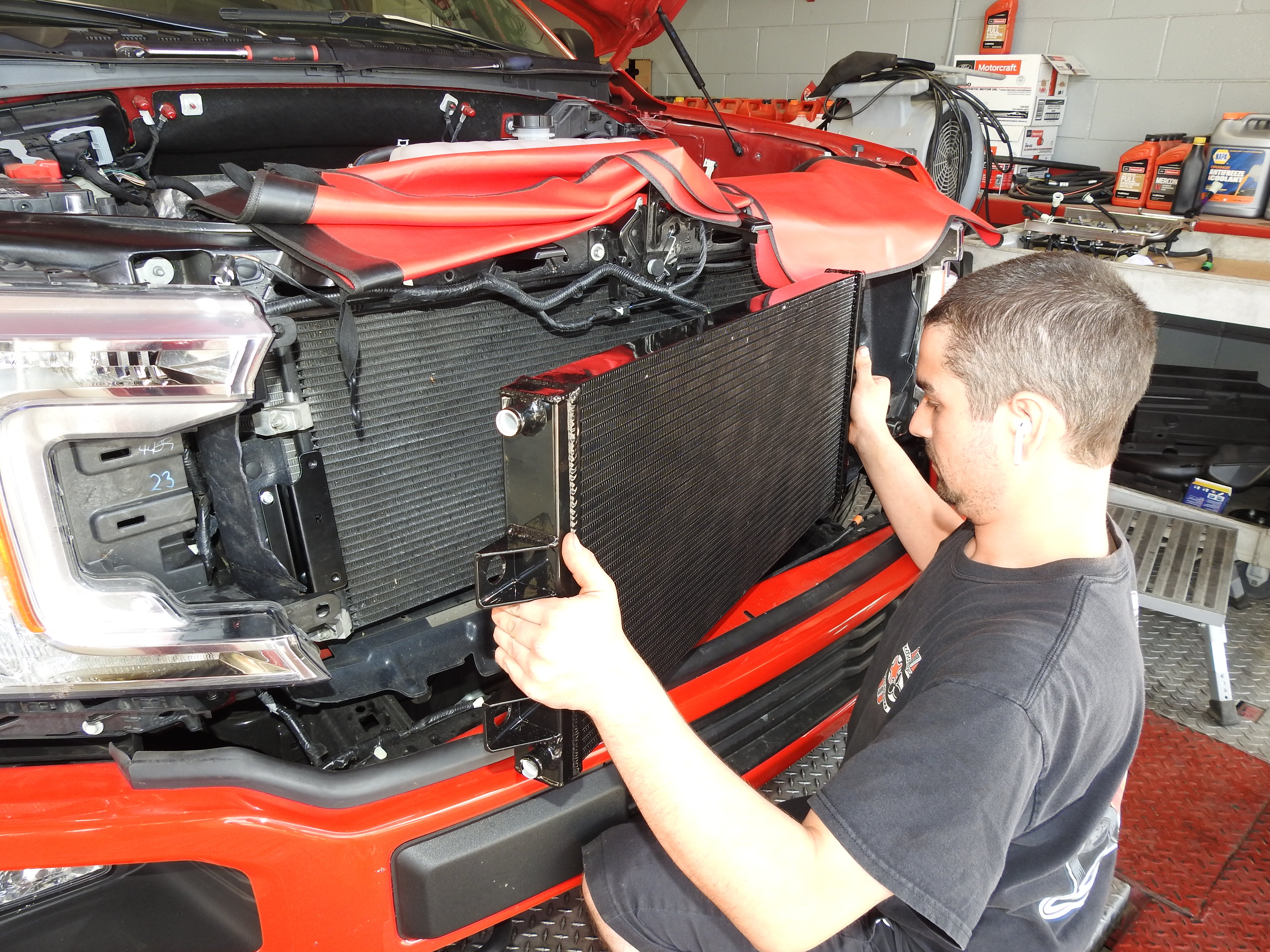
Parker Ruiz from Whipple began by disconnecting the fuel pump control module electrical connector and battery, before draining the coolant and removing the radiator shroud. Our F-150 doesn’t have a front camera, but if it did, that connection would need to be undone, along with the windshield washer fluid connection. Both the upper and lower grille shell section were removed. All connections were undone to allow for the removal of the factory airbox, and all lines to the intake manifold, including both brake booster quick connect lines, EVAP solenoid electrical connector, electronic throttle electrical connector, and others were removed. The heater tube on the passenger side of the block was removed, before disconnecting the driver side heater tube quick connect fitting and carefully removing the factory fuel line.
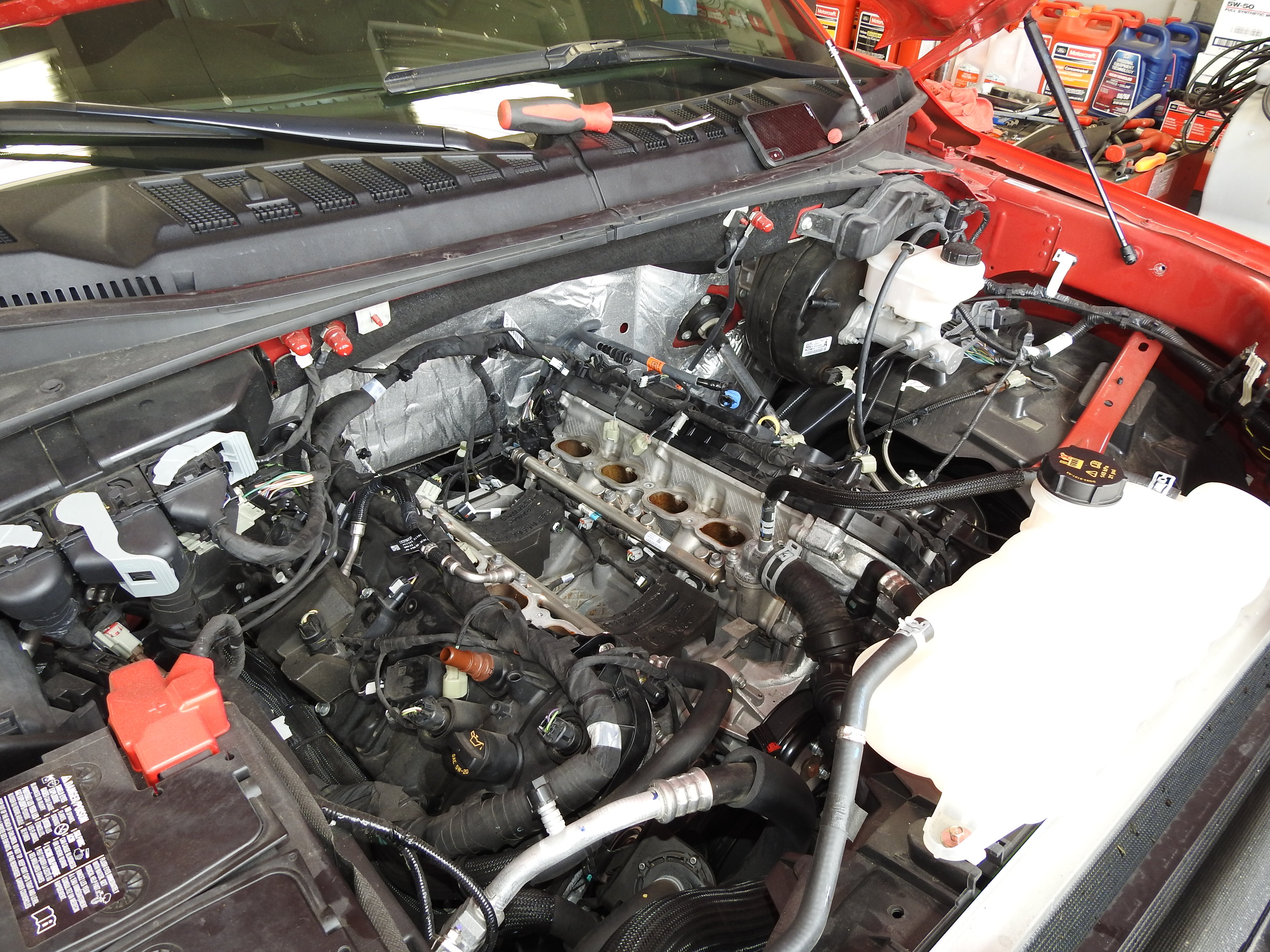
After removing the feed line from the factory port injection system to the direct injection mechanical pump, as well as the fuel rail foam covers, and disconnecting all fuel injector connectors, you will need to loosen the four bolts holding the fuel rails down, and the eight manifold-to-cylinder head bolts. The push pin from the engine loom tied to the intake manifold was removed and the intake manifold could be removed from the engine. After cleaning the intake manifold to cylinder head surface and installing tape over the exposed ports, the intake manifold runner control (IMRC) solenoid and IMRC position sensor connectors were covered with electrical tape and secured to the factory loom at the rear of the engine. Then the actual installation could begin.
The supplied temperature manifold absolute pressure (TMAP) pigtail was connected to the stock MAP sensor connector to await installation to the TMAP sensor later. The supplied spark plugs were then gapped to .028-inch before applying a light coating of anti-seize and installing. The coils were then reinstalled onto the plugs.

The water pump pulley was removed before needle nose pliers were used to rotate the factory pinch clamp at the water neck towards the driver side for future clearance of the supercharger. After switching the stock O-ring from the factory bank 2 heater to the newly supplied one and installing it into the port, the electric circulating pump and bracket were removed from the engine. Three factory fasteners were removed that connected the timing chain to the head cover, and one from the water pump (for the new idler plate).
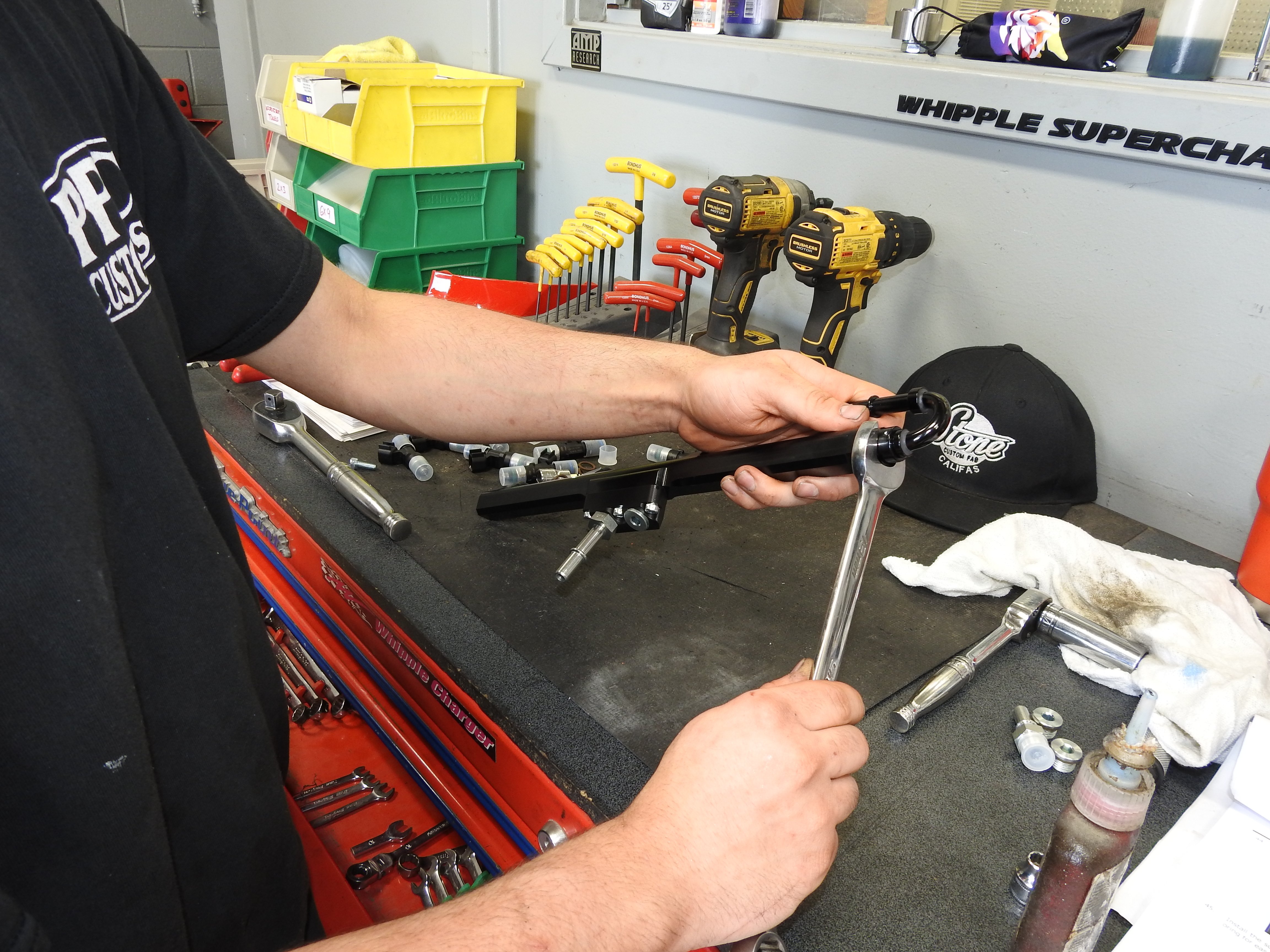
The supercharger support bracket was then installed onto the back of the idler plate, but left loose for now. Three support stands were installed onto the front idler plate, and the idler plate was secured to the engine. The four supplied O-rings were installed onto the fuel rail adapters before installing the fuel rail adapters to the fuel rails. Then, the fuel PSI sensor was removed from the factory fuel rail and installed onto the adapter. After equipping with O-rings, the inlet and outlet fittings were installed into the fuel inlet block. The supplied -6 ORB plug was then inserted into the extra port. Two more O-rings were installed onto the inlet and outlet fittings before installing the fittings into the rear side of the fuel rails. The supplied injector shims were installed to the injector port of the supercharger housing. Then, the fuel injectors were installed to the fuel rail, and the supplied fuel injector position lock brackets were installed to clock the supplied fuel injectors into the correct position.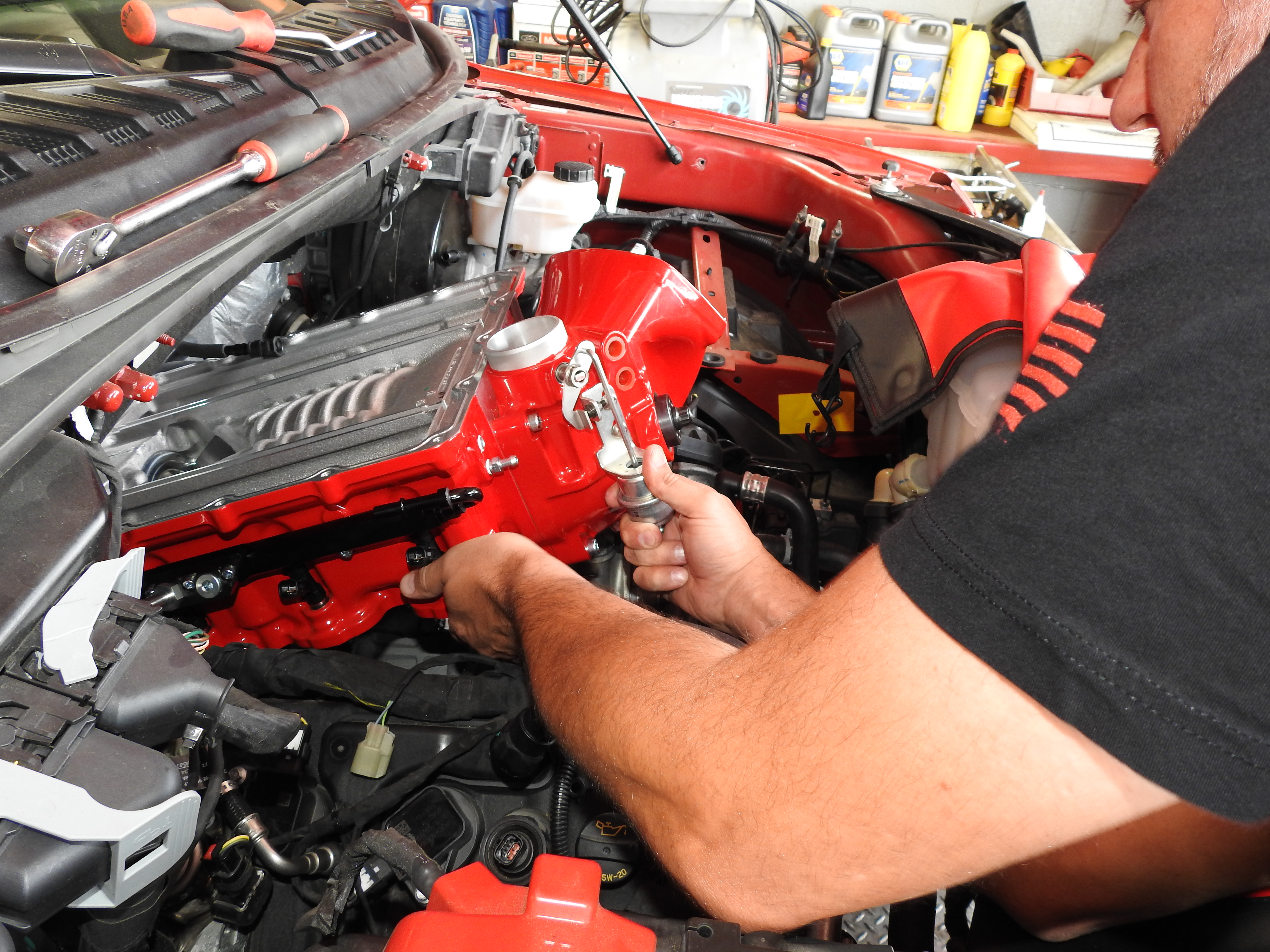
The fuel injectors, rails, and lock bracket were installed to the intake manifold and secured, before the supplied fuel crossover line was installed around the back of the supercharger. The supplied bypass actuator was installed onto the bypass nipple and nipple on supercharger housing before securing with a zip tie. Three supplied O-rings were installed into the supplied quick connect fittings, before the fittings were installed into the proper ports, and the supplied 6AN plug with O-ring was installed into the lower port of bank 1. The supplied silicone tube was used to install the 80.5-inch cord using Whipple’s illustration to route it correctly.
A supplied pre-formed O-ring was installed onto the top sealing surface of the supercharger housing. Then, the supplied 3-bar TMAP sensor was installed onto the front of the intake manifold and the eight supplied manifold O-rings were installed into the Whipple intake manifold.
After ensuring that the supercharger was on a flat surface, the oil fill plug was removed and the compressor was filled to the bottom of the fill plug (4 fluid ounces). The compressor was rocked back and forth before the compressor/rotors were spun by the pulley so that the oil would fill the bearings.
The previously installed tape was removed from the cylinder head’s exposed ports and the surface was cleaned, before the supercharger housing (without the lid) was installed onto the engine. Four supplied bolts were installed in the outer bolt holes and six larger bolts with supplied O-rings were installed under the head. Supplied bolts were secured to the front support bracket, before torquing all ten manifold bolts in a specific pattern. The water pump pulley was then reinstalled, and a supplied internal bypass O-ring was installed to the lid bypass passage.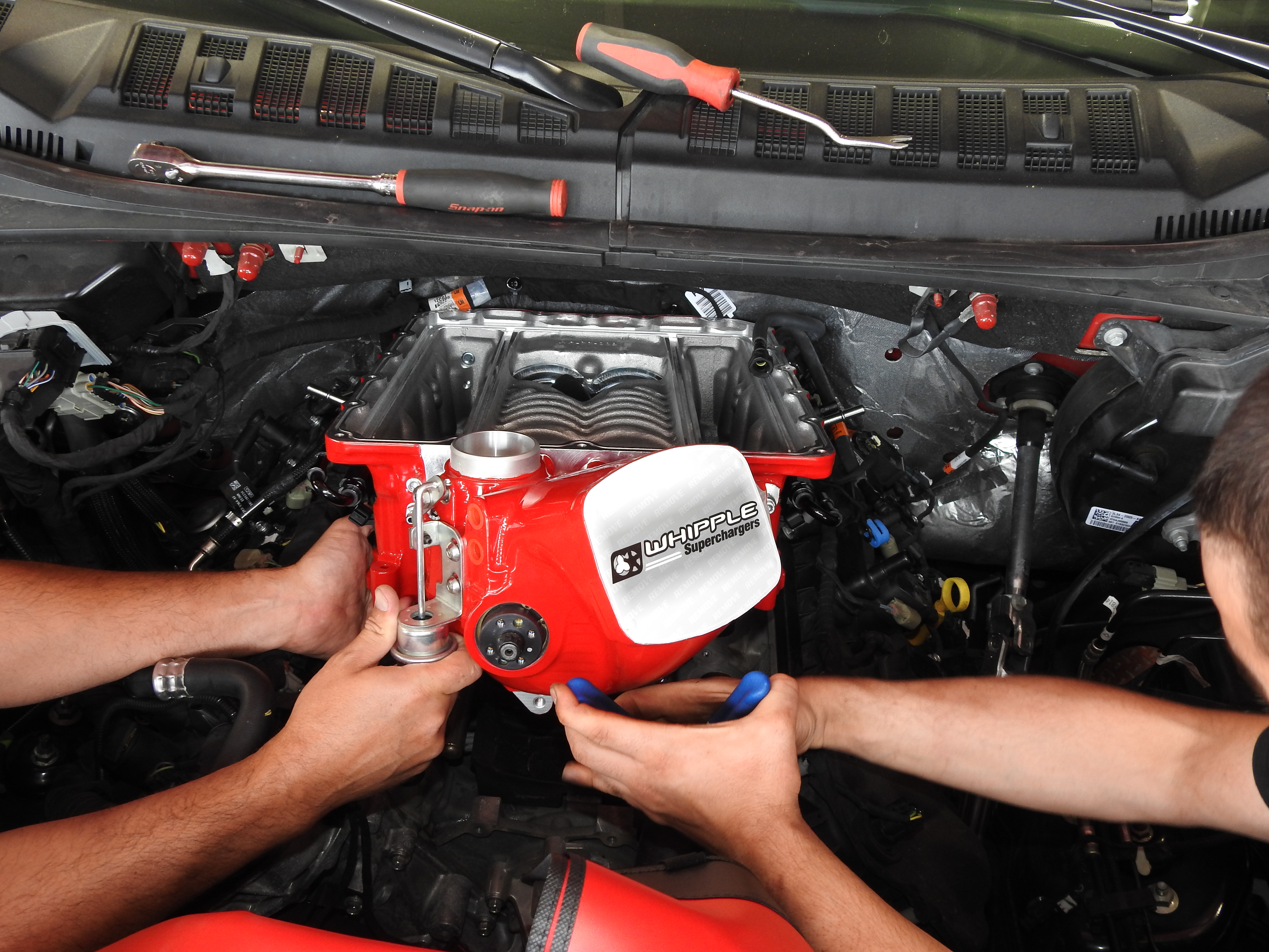
The supercharger lid was then installed onto the supercharger housing, carefully placing the bypass down. The lid was secured with a total of 20 bolts in a specific pattern. The evaporative emissions canister purge valve (EECPV) bracket was slid under two bolts. The factory passenger side rail fitting was then connected to the DI pump factory hose and the factory fuel inlet line was connected to the driver side fuel fitting. Then, the factory fuel PSI sensor connector was connected to the sensor. The EECPV was slid to the previously installed bracket before the factory plastic quick connect fitting was connected to it. The two-way electrical connector was also connected to the EECPV.
A supplied hose with a quick connect fitting was installed to the EECPV barb fitting and upper quick connect fitting on the supercharger’s inlet. A supplied brake aspirator hose was installed from the brake booster to the lower quick connect fitting on the supercharger inlet. Then, a supplied PCV hose was installed to connect the passenger side valve cover and the supercharger inlet via quick connect fitting. Eight fuel injector electrical connectors were plugged into the new fuel injectors. The water neck vent line hose clamp was rotated to face forward to avoid leaks, and the factory heater hose quick connect was connected to the factory heater tube, before connecting the factory heater hoses to the previously installed plastic water fitting.
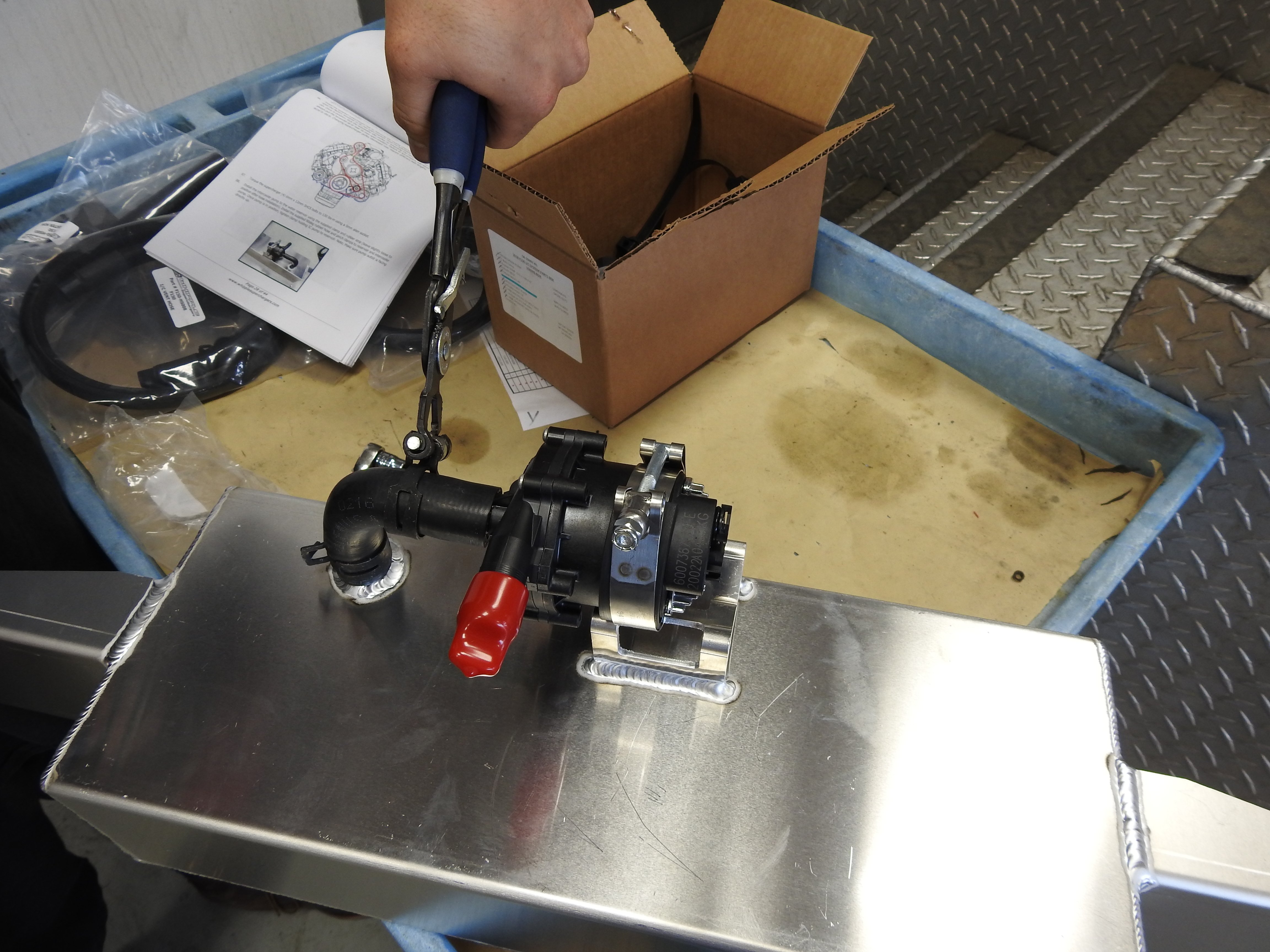
Utilizing the supplied step spacer and the t-nut in the idler plate, the supplied smooth idler pulley was installed. Then, the supplied grooved idler pulley was installed onto the idler plate using included step spacers. The supplied circulating pump bracket was secured to the valve cover stud. The stock circulating water pump was installed onto the new bracket using supplied t-bolt clamp and rubber strip before reconnecting to the factory hoses utilizing stock clamps. Then the supercharger pulley was installed.
Using Whipple’s routing diagram, the supercharger belt was installed. The intercooler pump was connected to the water reservoir with a supplied clamp and rubber strip before installing the supplied rubber hose and pinch clamps.
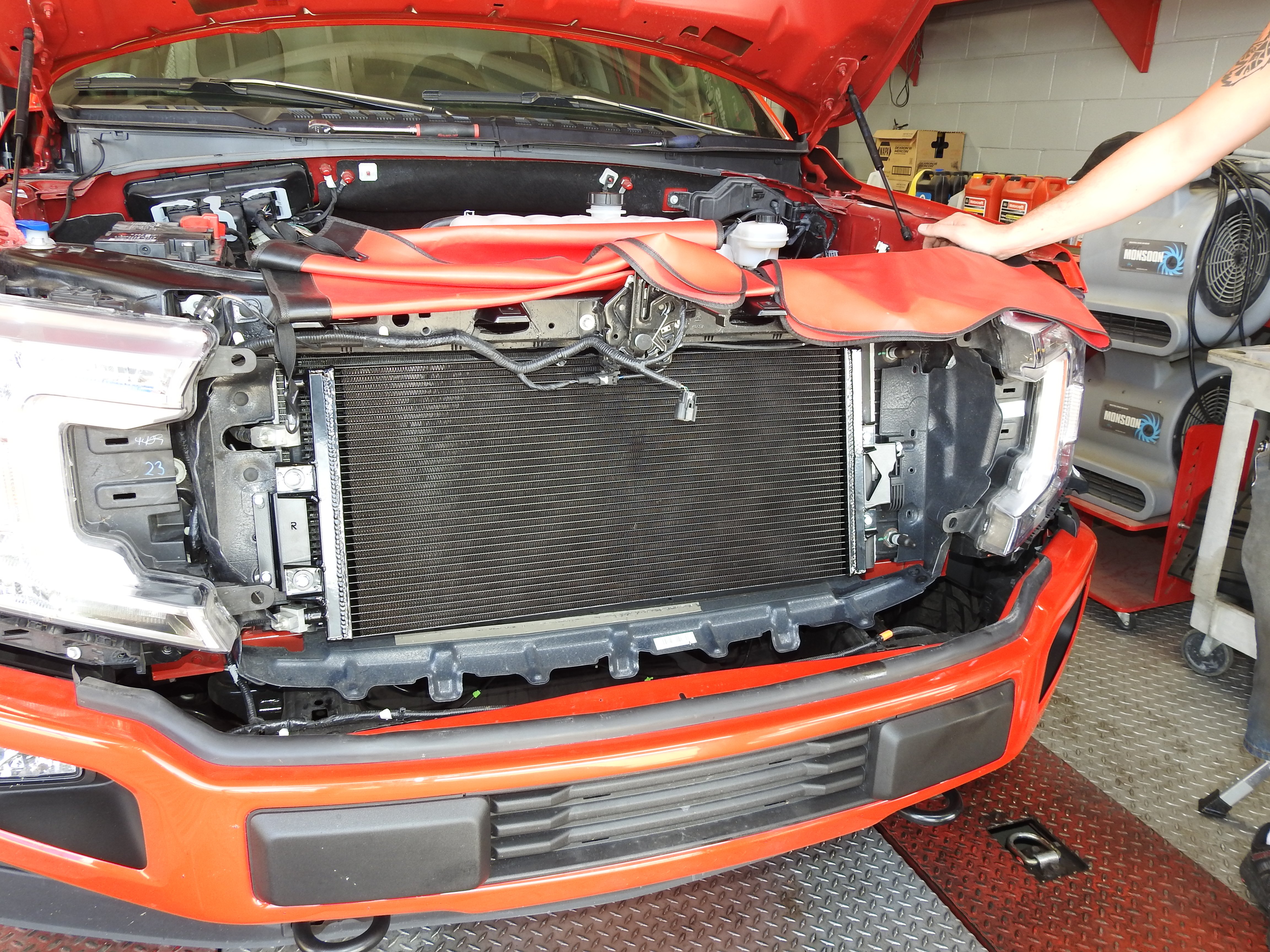
The factory radiator closeouts were removed from both sides of the radiator and the stock horn bracket and horns were also removed. The horns were then relocated from the factory bracket to the supplied version.
The low-temperature radiator was then installed, making sure that it wasn’t touching the factory radiator, and the horns were reinstalled. Then, the intercooler reservoir was installed. This was a multi-step, though relatively easy, process.
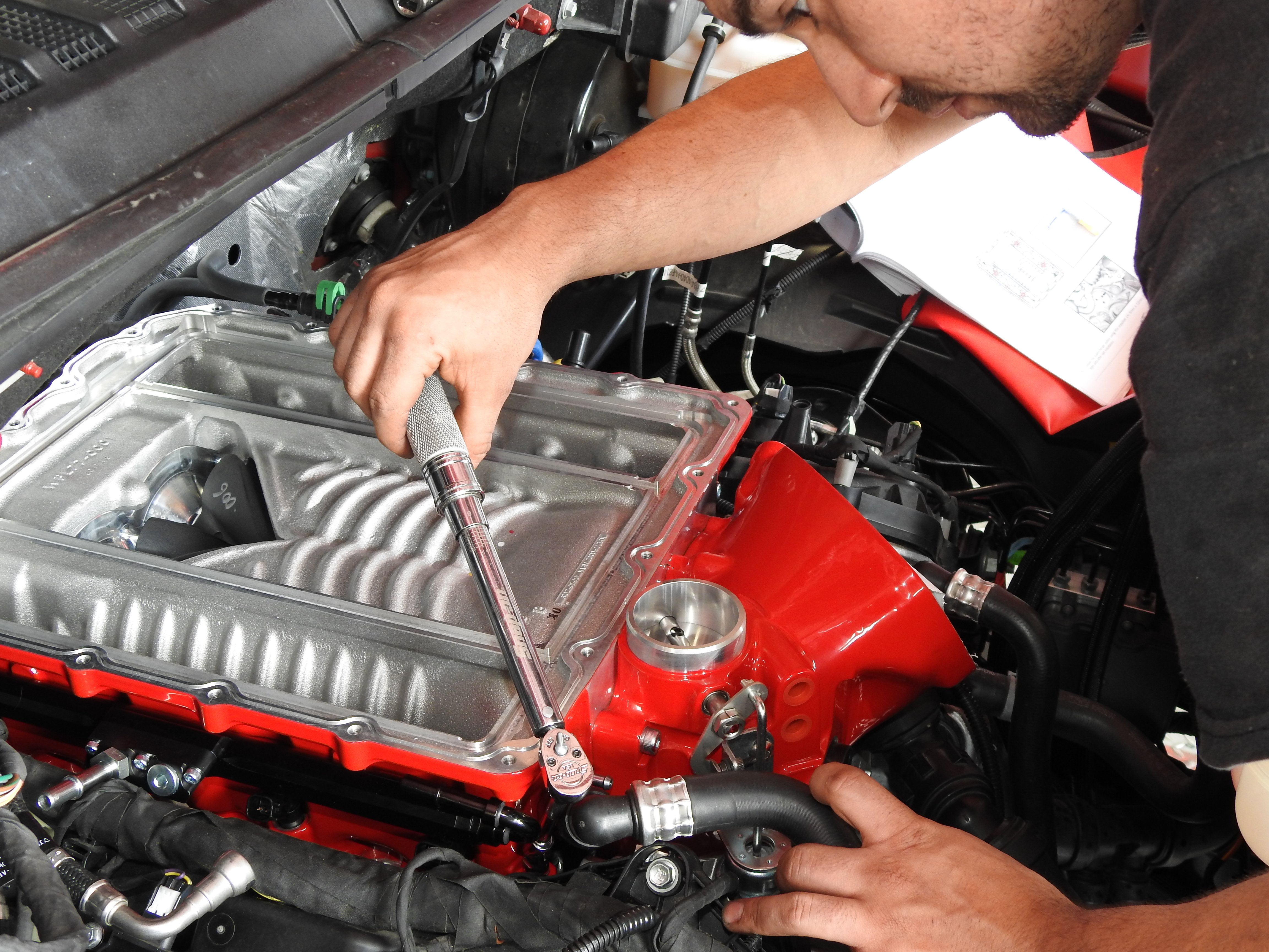

A supplied electronic throttle pigtail was then installed to the factory electrical connector and routed to the left side of the vehicle to be connected to the throttle body later. The throttle body included in the Stage 2 kit is Whipple’s 132mm Crusher throttle body, which was installed to the supercharger inlet using a supplied gasket and hardware. Then, the electronic throttle extension was connected to the electric motor.
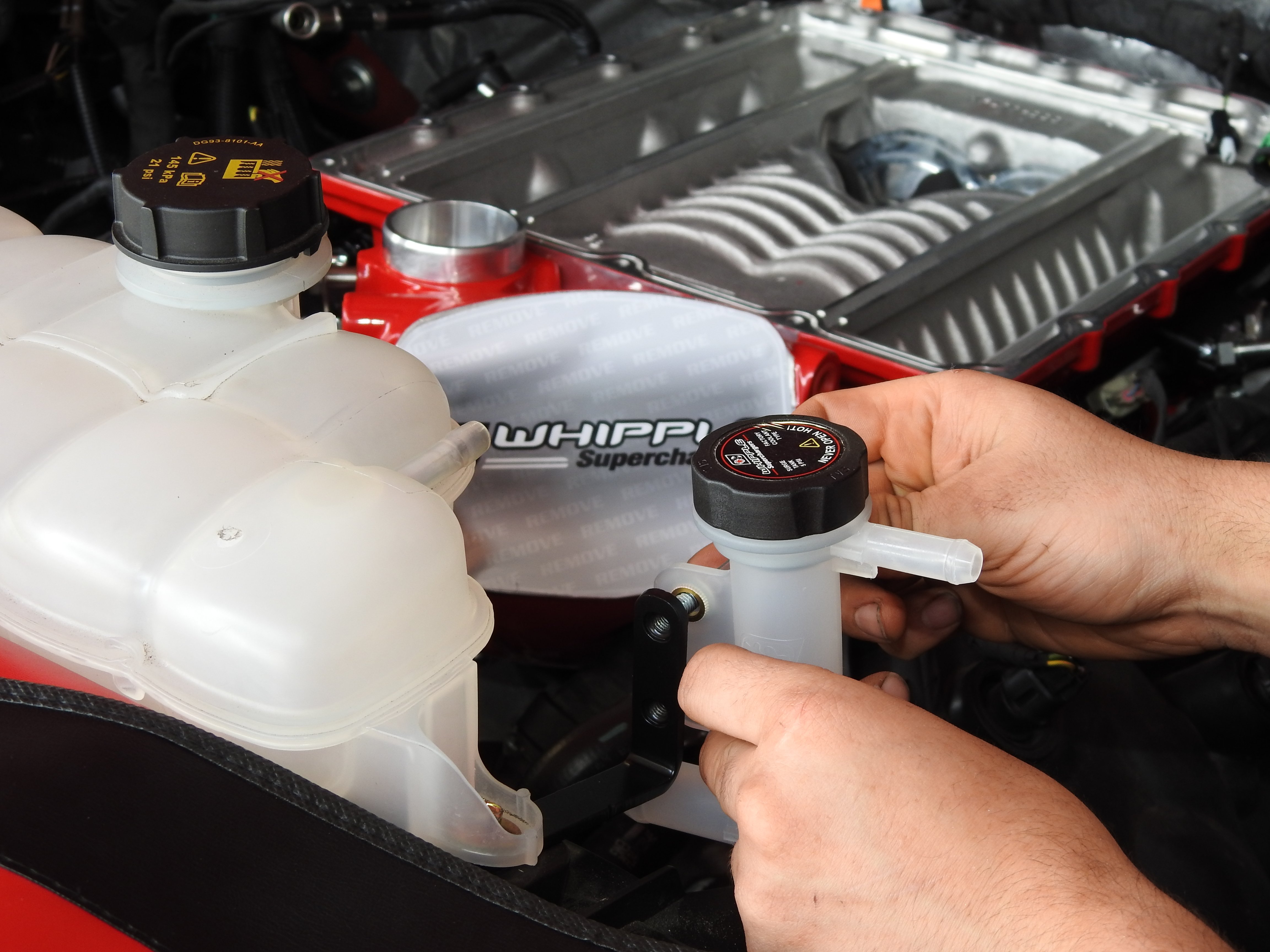
The stock coolant reservoir’s driver side bolt was removed to install the intercooler filler T-bracket under the coolant reservoir mounting tab before the bolt was reinstalled. The filler tee was then secured to the bracket, and the bracket secured to the valve cover. An included rubber hose was installed from the bank 2 outlet intercooler fitting to the intercooler filler neck and both ends were secured with pinch clamps. Then, the supplied lower airbox was installed in the factory location, fitted with its filter, and topped with the upper airbox.

A supplied rubber grommet was then installed onto the supercharger inlet tube with a quick connect fitting, and a supplied silicone hose was installed over the air inlet tube and airbox lid. Another silicone hose was installed over the throttle body before installing the air inlet tube between the filter and throttle body. One more silicone hose was slid over the throttle body before all ends were secured with the supplied hose clamps.
A supplied make-up air hose assembly was installed from the driver side valve cover to the quick connect fitting in the air tube. Using the stock hole in the battery box, a supplied push pin was used to secure the intercooler relay and fuse holder to the battery box before routing the power wire to the main power stud on the battery side. Then, the ground wire was routed around the front of the battery box and back toward the fuse box. The nut on the power stud (located on the positive battery connector) was removed, and the intercooler pump relay power eyelet was installed to the power stud on the battery’s positive stud and secured.
The ground bolt on the passenger side inner fender was removed, the intercooler pump relay ground eyelet was installed, and the factory bolt was replaced.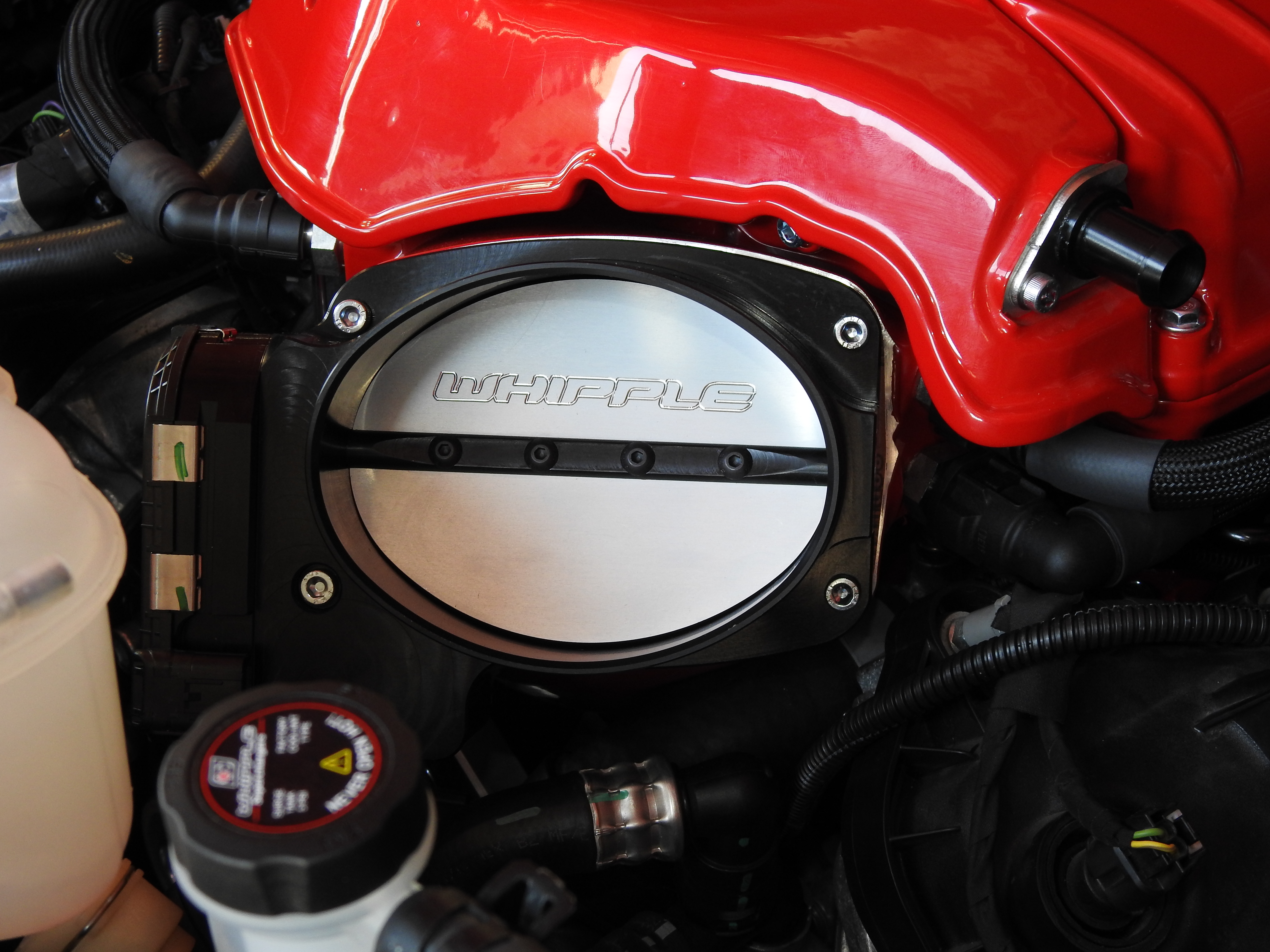
In the fuse box, the red 10 amp fuse from position #F17 (ABS) was pulled and placed in the unused fuse slot on the fuse tap. The supplied fuse tap was installed into the #F17 position. The relay/fuse was then secured with zip ties, ensuring that all other wires were clear of the belt system.
The engine coolant was replaced with a Ford approved engine coolant, and Whipple also recommends running two bottles of Redline Water Wetter. Finally, the battery was reconnected, and a 50/50 mixture of coolant and distilled water was added to the intercooler system, before the Tomahawk device was used to reflash the PCM. Once that was complete and the truck was ready to roll, the radiator shroud and grilles were replaced and previously removed connections made. Then it was time to hit the dyno!
Before and After Dyno Testing
Before heading over to Whipple headquarters, we decided to see where Project Red Storm was at in the power department from the factory. On the Ford Muscle in-house Dynojet dyno, the F-150 laid down a best of nearly 365 horsepower and a touch over 387 lb-ft of torque at the wheels. Because we understand that all dynos read a little differently, the decision was made to make one more baseline dyno test on Whipple’s in-house dyno. That testing resulted in a best pull of 350.49 horsepower and 351 lb-ft of torque.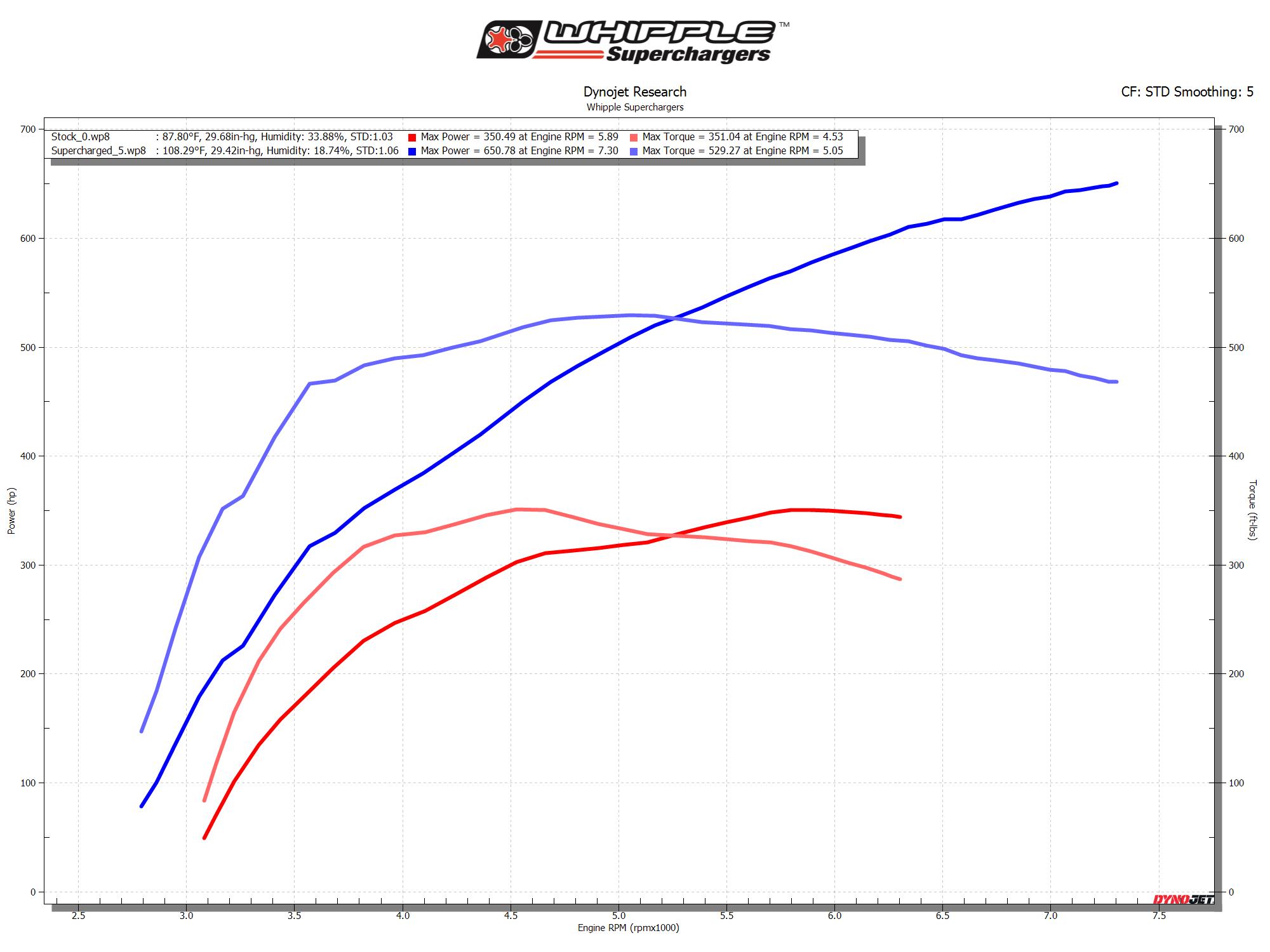
Finally, after the installation was complete and double-checked and calibration was worked out to a T, the truck let it rip to the tune of 650.78 horsepower and 529.27 lb-ft of torque at the wheels. That’s an addition of 300 horsepower and nearly 300 lb-ft of torque. Truly impressive stuff on an otherwise stock (and emissions-legal) truck!
“The whole project has been incredible from the initial installation process to the performance gains that we achieved,” Dave said. “Dustin and the people at Whipple have been great to work with, and have put together a kit that has superseded all of my expectations. I’m looking forward to the upgrades to come to see what kind of power we can make out of this Gen V 3.0-liter Whipple supercharger.”
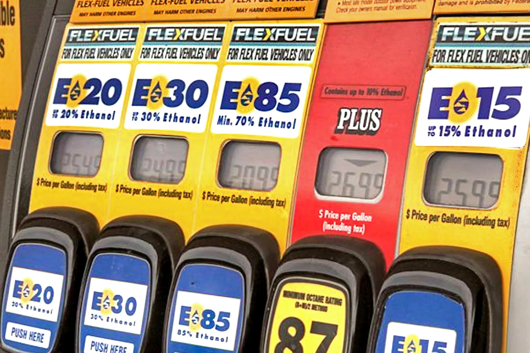
In the next installment of the Project Red Storm saga, we’ll get to work squeezing more horsepower out of the F-150 with a conversion from SMOG-legal to “race-ready” and the addition of E85 and custom tuning. Stay tuned!