By now, you should be very familiar with our project truck that we call Project F-Word. We have grand plans for this ’69 F100, which includes a complete build and occasional autocrossing, and maybe a few runs down the dragstrip as well. Today’s installment was long-anticipated and fun; dropping in the Gen3 Ford Performance Aluminator crate engine (M-6007-A50NAB) and Tremec T-56 Magnum 6-speed transmission. This is a pretty straightforward drop-in installation if you use all the necessary parts, most of which are available from Ford itself.

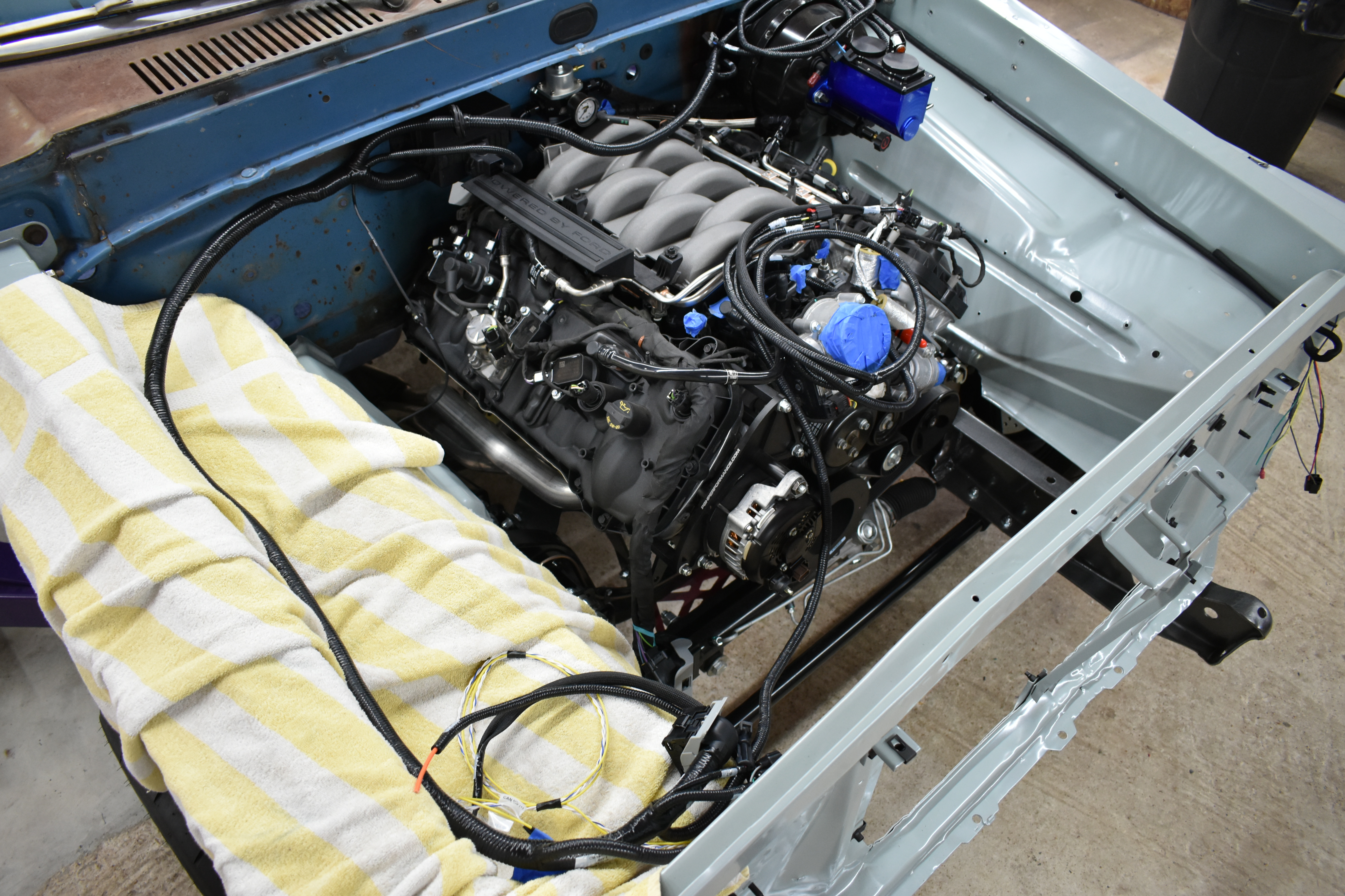
Project F Word as it sits, after the Coyote Aluminator was installed but before it was all wrapped up. This is gonna be fun!
We wanted a Coyote engine in this project because we love the high-revving nature and performance that it delivers. We plan to drive this truck hard as we said in the opening paragraph, which prompted the call for Ford’s most popular crate motor. This isn’t just an engine that has been pulled from a wrecked 2020 Mustang, it’s called the Aluminator—read all about it here.
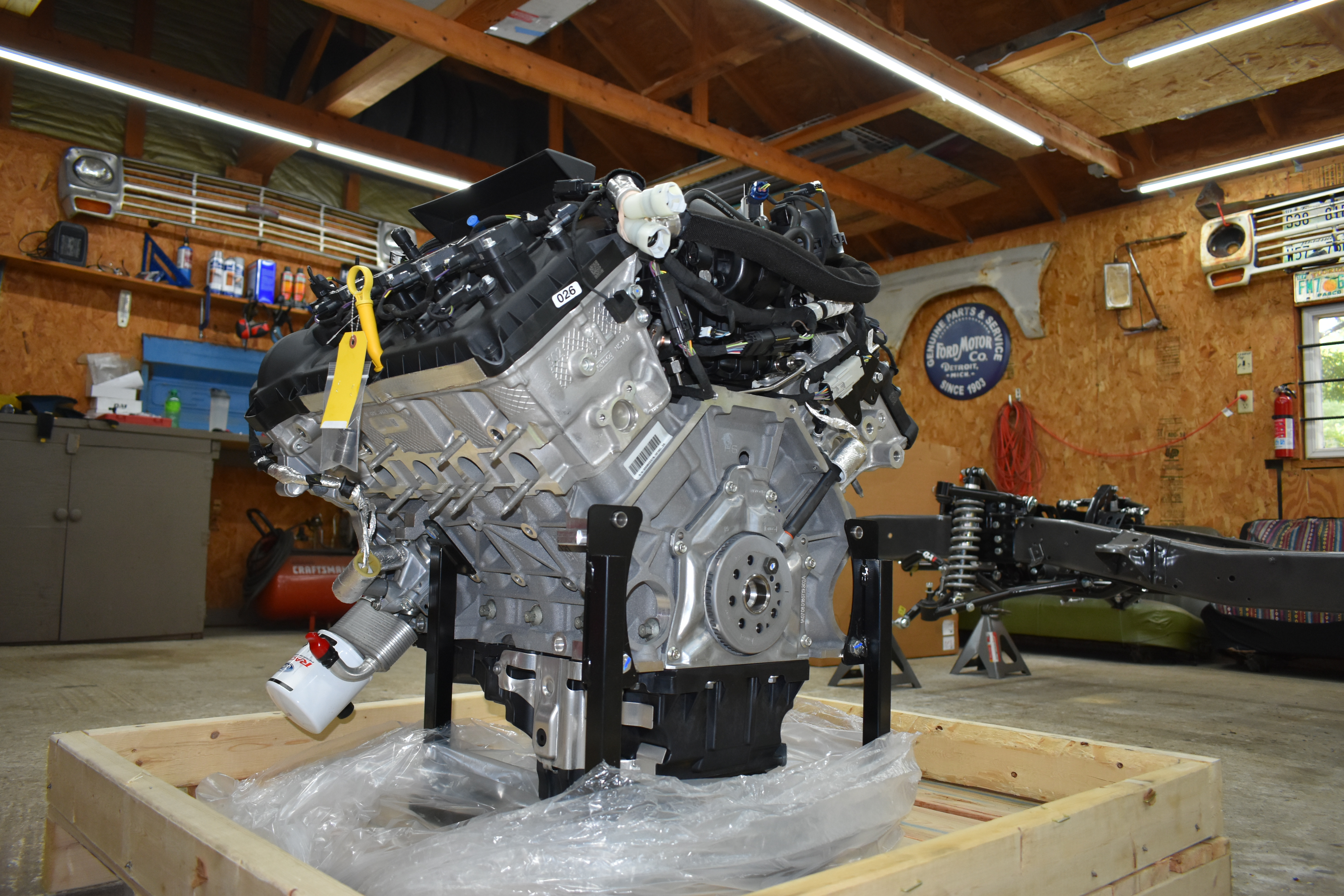
Once unboxed, the GEN3 Coyote 5.0L crate motor is nice and shiny. This is always better than spending an hour de-crudding an original engine. More powerful and far more reliable too.

A nice touch to the crate motor is that they are each hand-assembled and signed—this one was screwed together by Robert Garcia.
We were lucky enough to be able to place an early order with Ford Performance for its new Gen3 Aluminator, so lucky that it turned out we received serial number 001. When we ordered our engine from Ford Performance we also ordered some parts that we knew we would need to get the engine in the truck and running, and allow this to go in the truck easily and make everything fit and work.
Ford Performance Parts List
- Engine - Gen 3 NA - (12:1 CR) - Aluminator Coyote Engine - M-6007-A50NAB
- Control Pack - Manual transmission - M-6017-M50B
- Oil filter adapter kit - M-6881-M50A
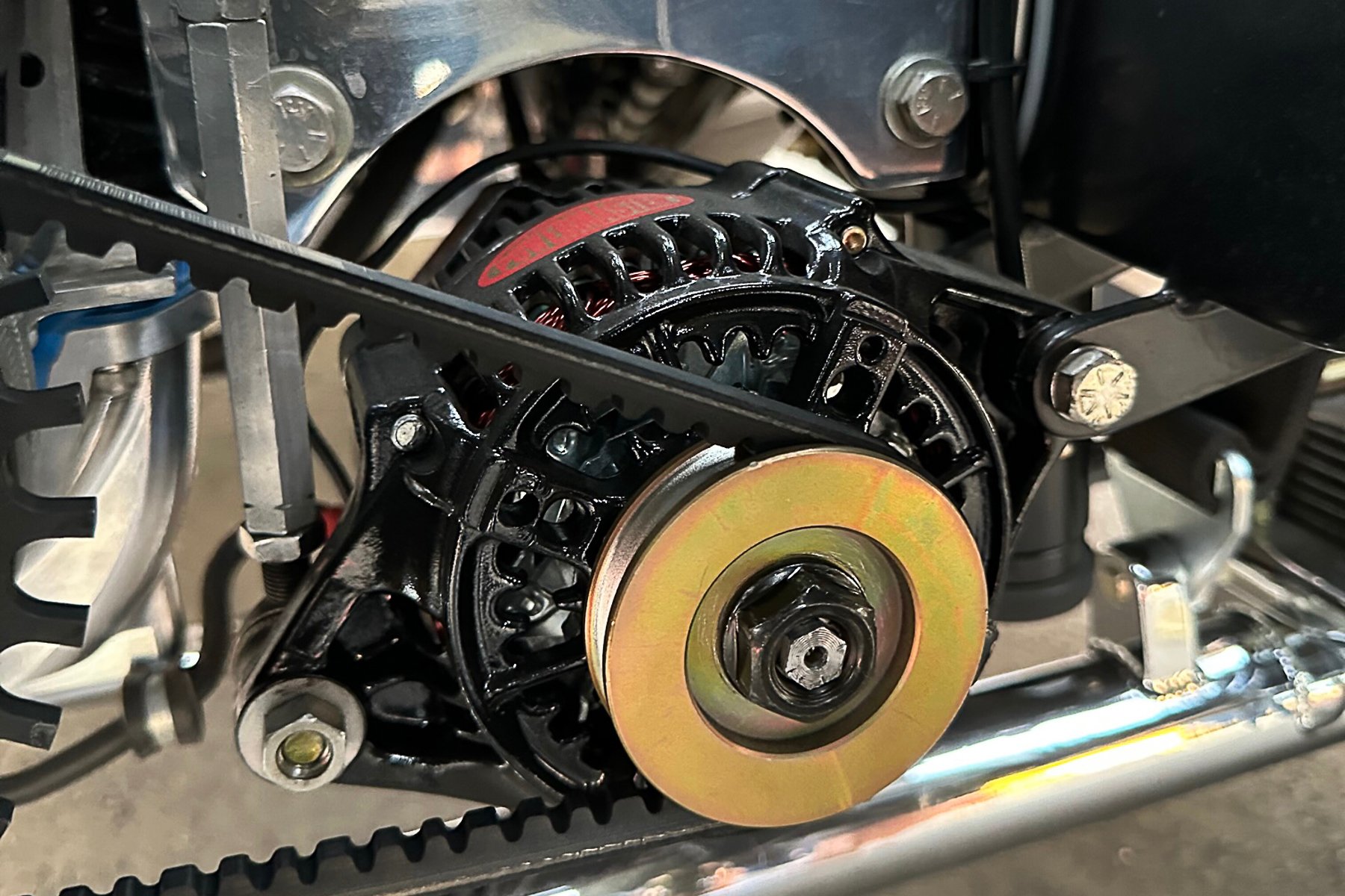
- Alternator kit - M-8600-M50ALTA
- Starter kit - M-11000-C50

The big-box hides the crate motor and the smaller box on top is the Control Pack, which is essentially the ECU, wiring harness, and drive-by-wire throttle pedal that makes it all a no-brainer to install the engine in a non-computer-controlled vehicle, like our 1969 F100 pickup.
Since our truck was just a bare frame with QA1 front suspension at this point it was very easy to set the engine in. But first, we needed to remove the factory Mustang oil filter housing, which fits the new Mustang just fine but does not clear much older chassis, so we had to install the Ford Performance Oil Filter Adapter Kit. We needed the additional clearance and with the factory housing, the oil filter would not clear the QA1 crossmember. It’s important to note that the adapter does not use the factory oil bypass solenoid that is normally mounted on the factory filter housing. The good news is that our Control Pack ECU doesn’t require this signal to function properly.
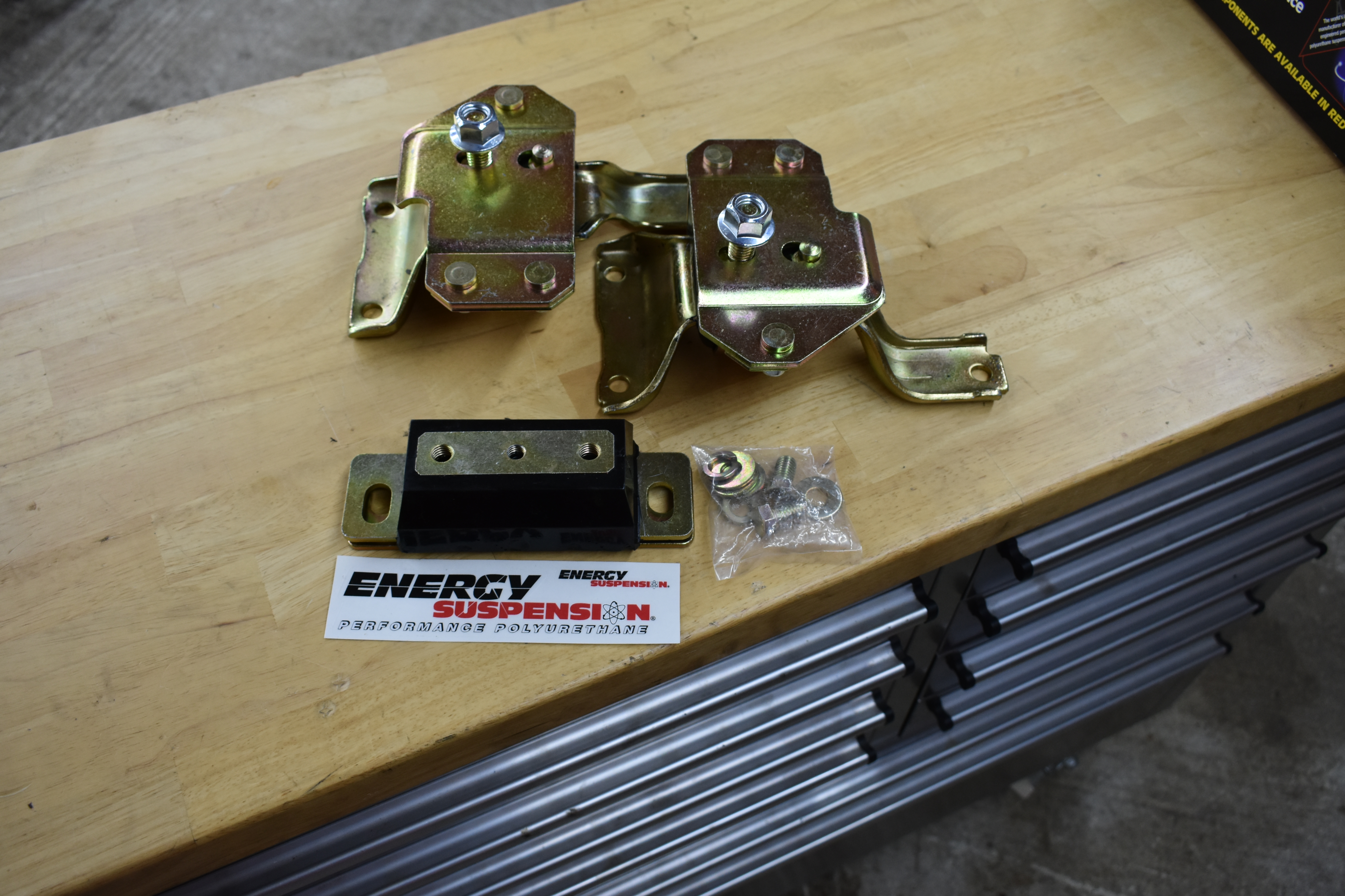
To mount the engine to our chassis (which is stock but upgraded with QA1 suspension) we used Energy Suspension motor and transmission mounts (PN 4.1127G and 4.1104g respectively). These were designed to accept the ‘99-‘04 Mustang V8-specific engine mounts.
Once we had the oil filter adapter mounted to the block we could install our Energy Suspension motor and transmission mounts and drop the combo between the frame rails. The QA1 engine mounts were designed to accept the ‘99-‘04 Mustang V8 specific engine mounts and here is what we ordered.
Energy Suspension Parts List
- Motor Mounts - Energy Suspension PN # 4.1127G
- Trans Mount - PN # 4.1104g

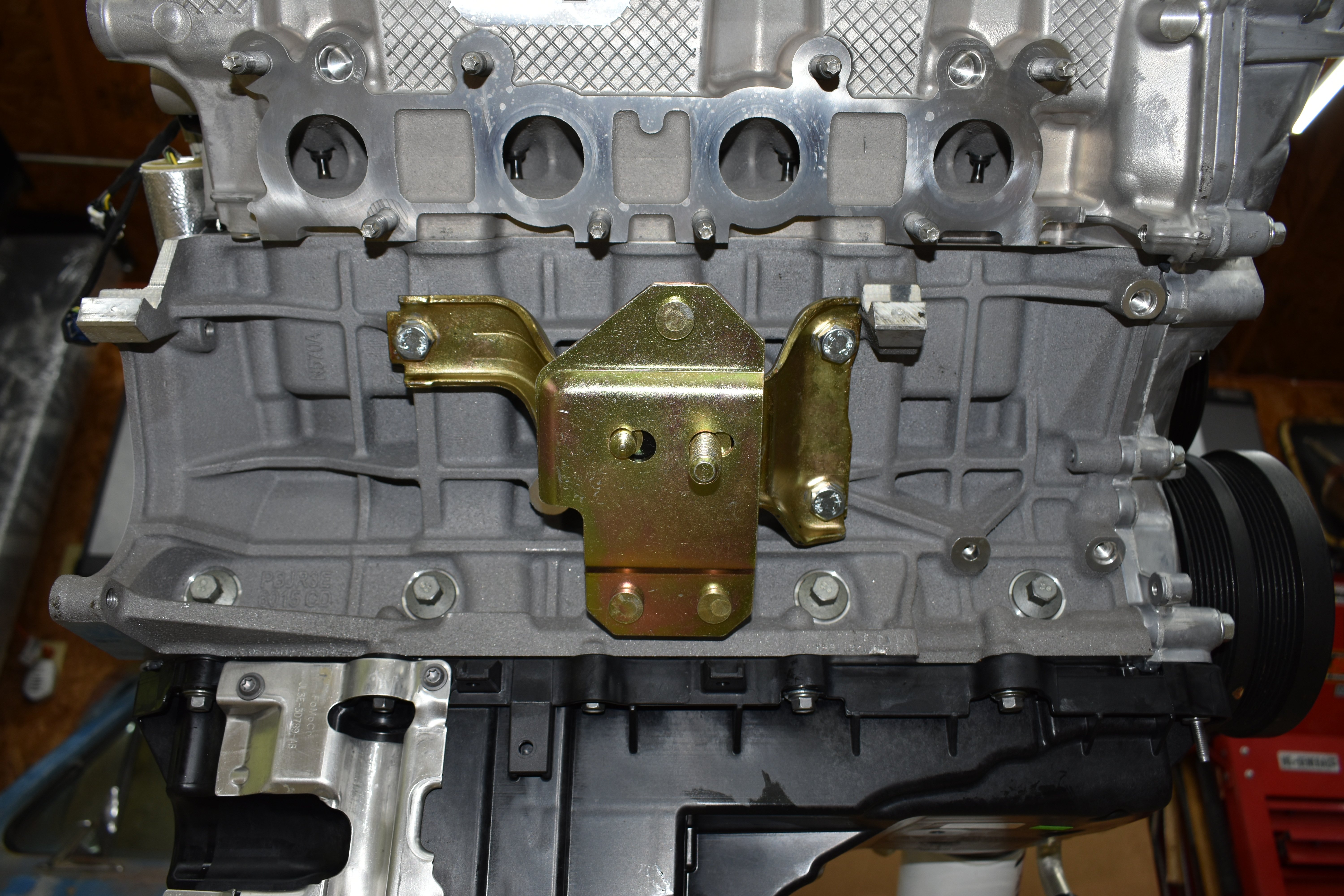
The Energy Suspension mounts attach like this, with a few simple bolts.
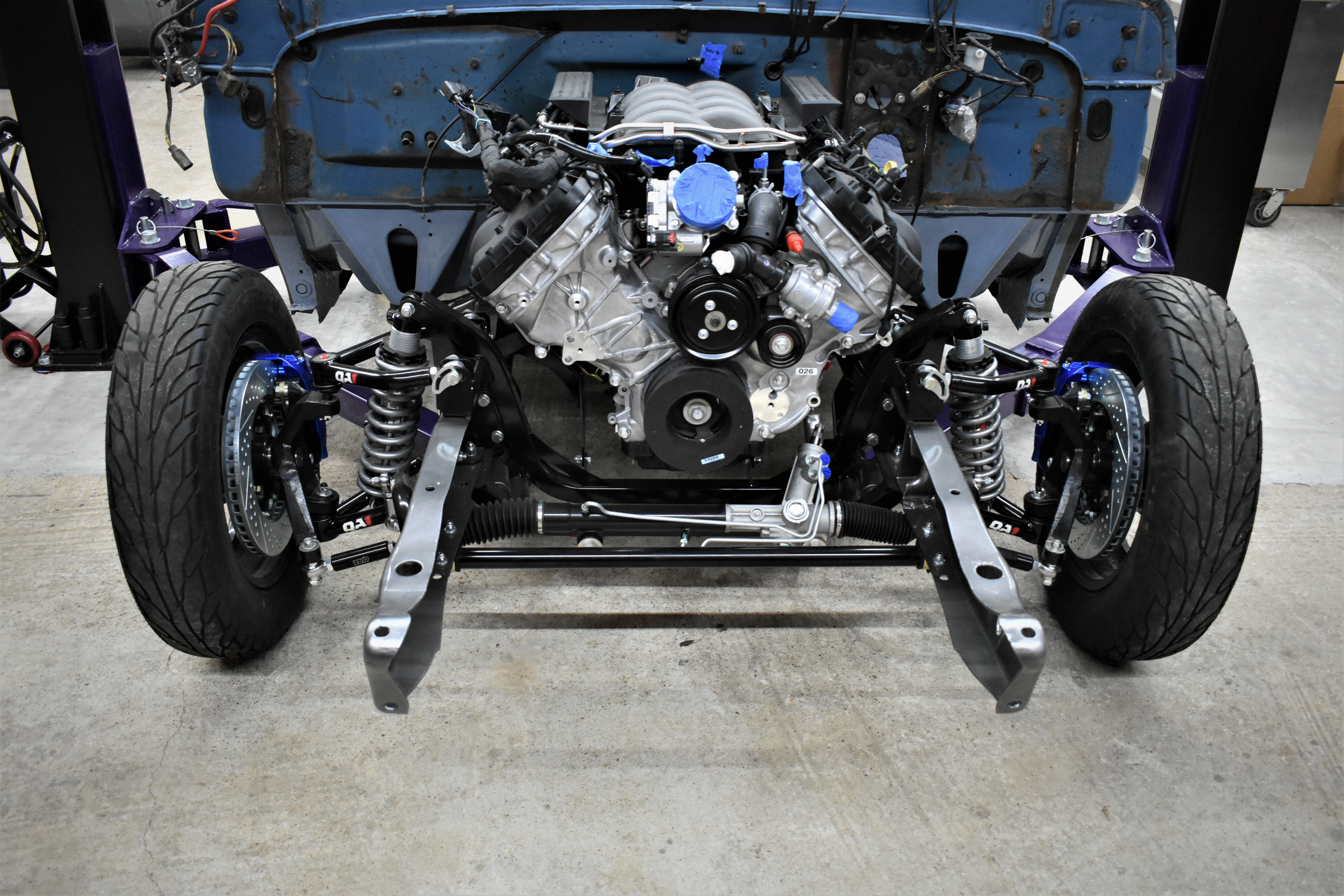
With the mounts bolted on the engine settled nicely into place. Thankfully, the F100 has a roomy engine compartment that clears everything with room to spare.
With these extra parts, dropping the engine in and securing it was an easy process that only took a few hours, then it was time to lay on our back and get dirty installing the transmission (we didn’t use a vehicle lift—next time!). To mate the Tremec 6-speed to the shiny new Gen3 Coyote, we needed a Quick Time bellhousing (PN RM-8080) from our friends at Holley. At this point, we needed some advice from our friends at Silver Sport Transmission (SST). Originally when we installed the T-56 Magnum with SST they bolted it to the big-block Ford FE engine, but the bellhousing is obviously different than what fits a Coyote, so we spoke with VP of Sales and Marketing Jeff Kauffman and he set us up with everything we needed to get the Coyote and T-56 Magnum to bolt together.
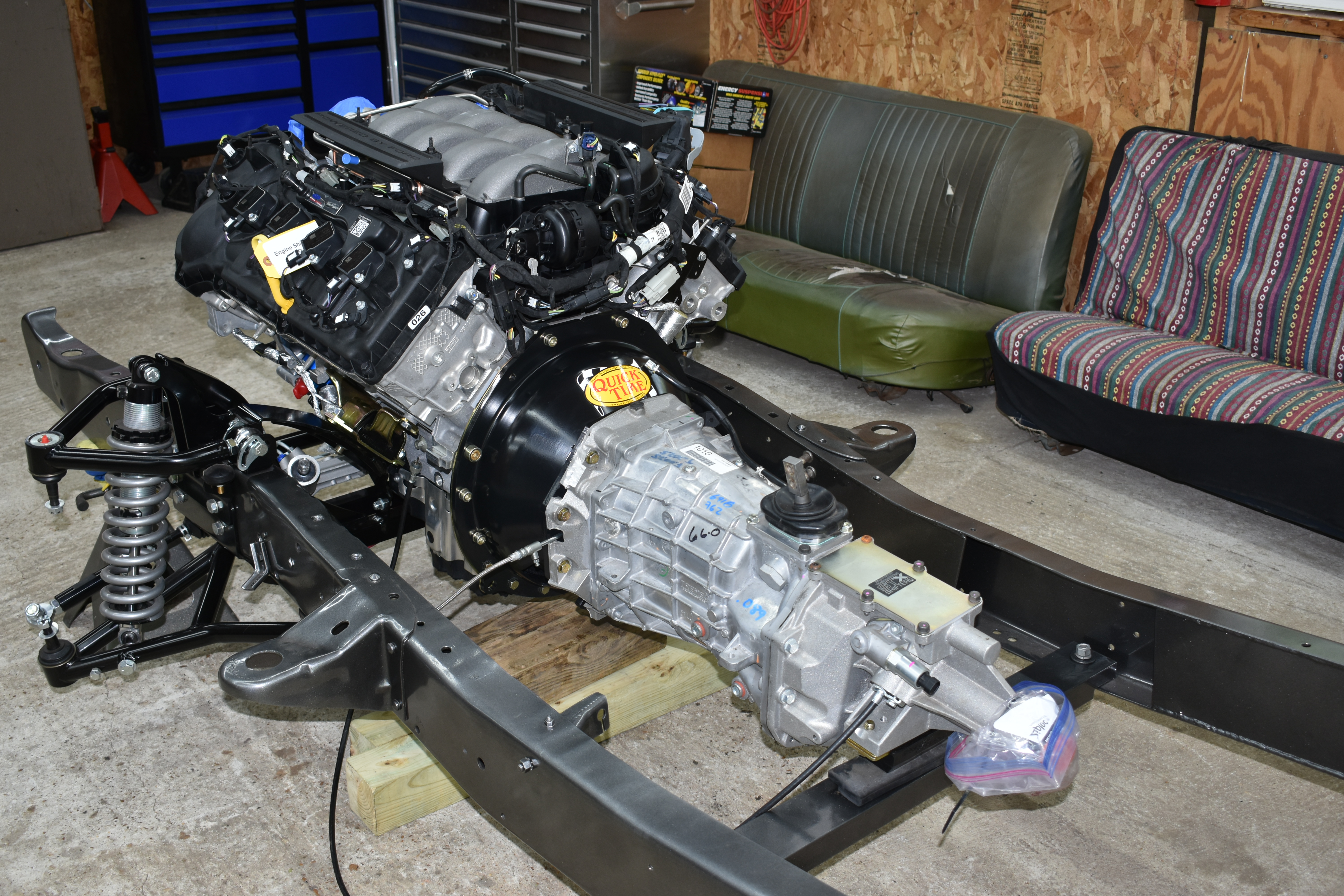
Silver Sport Transmission (SST) has been friends of ours for a while now and were our choice to source a Tremec T-56 Magnum 6-speed, and some other parts as well. Here it is hung behind the Coyote in the F100’s chassis. Notice the Quick Time bellhousing that makes hooking it up to a Coyote easy.
It’s an advantage to have friends like Jeff and his team at SST because we know we would get the correct parts and their technical knowledge and support is awesome to make sure you set everything up correctly. Since the Coyote engine is high revving and we plan to shift this thing at 7,500-8,000 RPM, there were some specific procedures we needed to follow to make sure the bellhousing, clutch, and input shaft were all aligned with the center of the crankshaft and within a tolerance that SST considered acceptable. If we were out of spec even by a small increment it would create a side load on the gears and could cause premature wear, clutch chatter, noise, and shifting issues. This has always been an issue with installing aftermarket manual transmission parts if you don’t properly align the bellhousing, especially if it’s an aftermarket housing. The acceptable spec by SST is 0.005, yes 5 thousandths of an inch. SST has a handy flyer that describes the procedure here.
As the installation manual states, “The goal is to align the input shaft of the transmission with the center of the crankshaft. Unlike the old 3- and 4-speed transmissions, all TREMEC 5- and 6-speed transmissions have tapered roller bearings that are shimmed for in-and-out play. If the transmission is not aligned with the crankshaft it will create a side load on the gears and potentially cause premature wear, clutch chatter, noise, and shifting issues.”
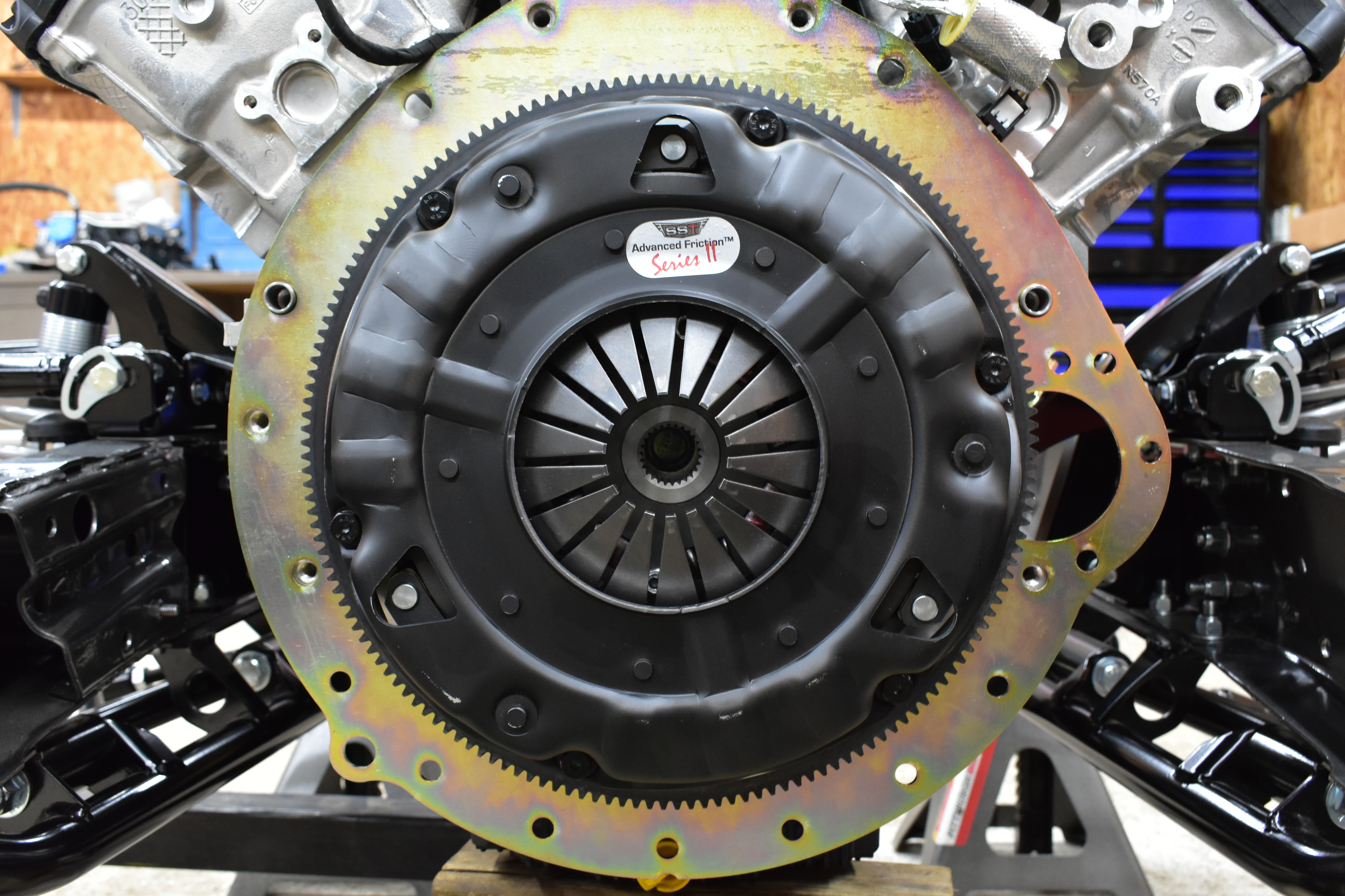
For a clutch, we used SST’s Advanced Friction Series II unit, a billet steel flywheel, a new pilot bearing and ARP bolts.
Transmission Parts Needed
- SST Pilot Bearing - PN #PBF-M7600B
- SST Billet steel flywheel - 5.0 COYOTE - PN #FWFP-463408G
- SST Flywheel Bolts - PN #FWF-2542801
- SST Clutch - Advanced FrictionTM TRK Series II 11-inch clutch set (650 tq rating) - PN #CLA-TRK11-S2
- ARP Pressure Plate Bolts - PN #CAA-130-2201
Once we had the bellhousing aligned we sent our specs over to SST for their records so we can keep our warranty information up to date. The rest was pretty straightforward.
- Pull the bellhousing back off
- Install new pilot bearing
- Install the new flywheel with provided ARP bolts
- Align the clutch disk with the alignment tool
- Install the pressure plate and torque it in the star pattern as SST recommends
- Install the bellhousing
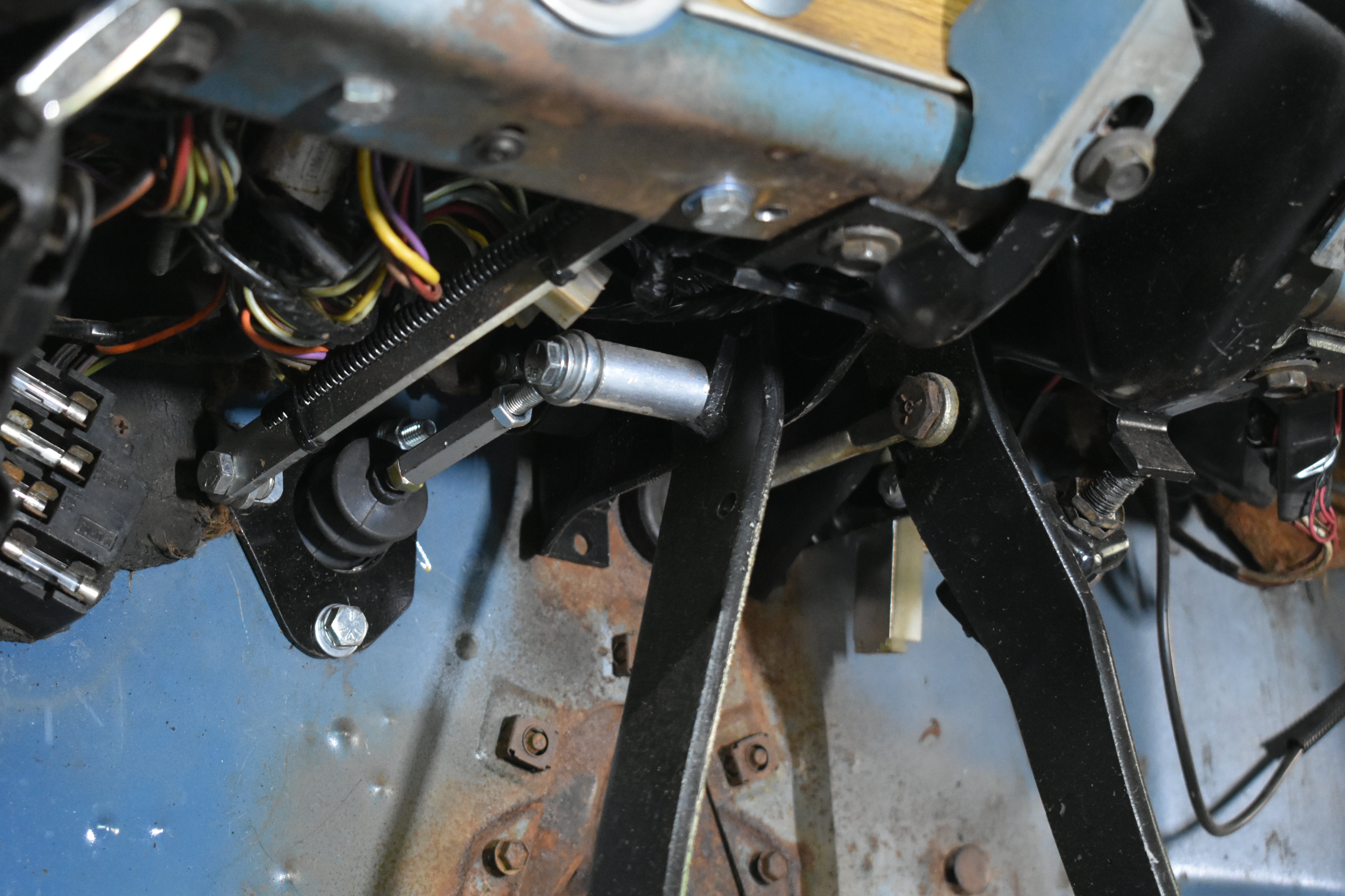
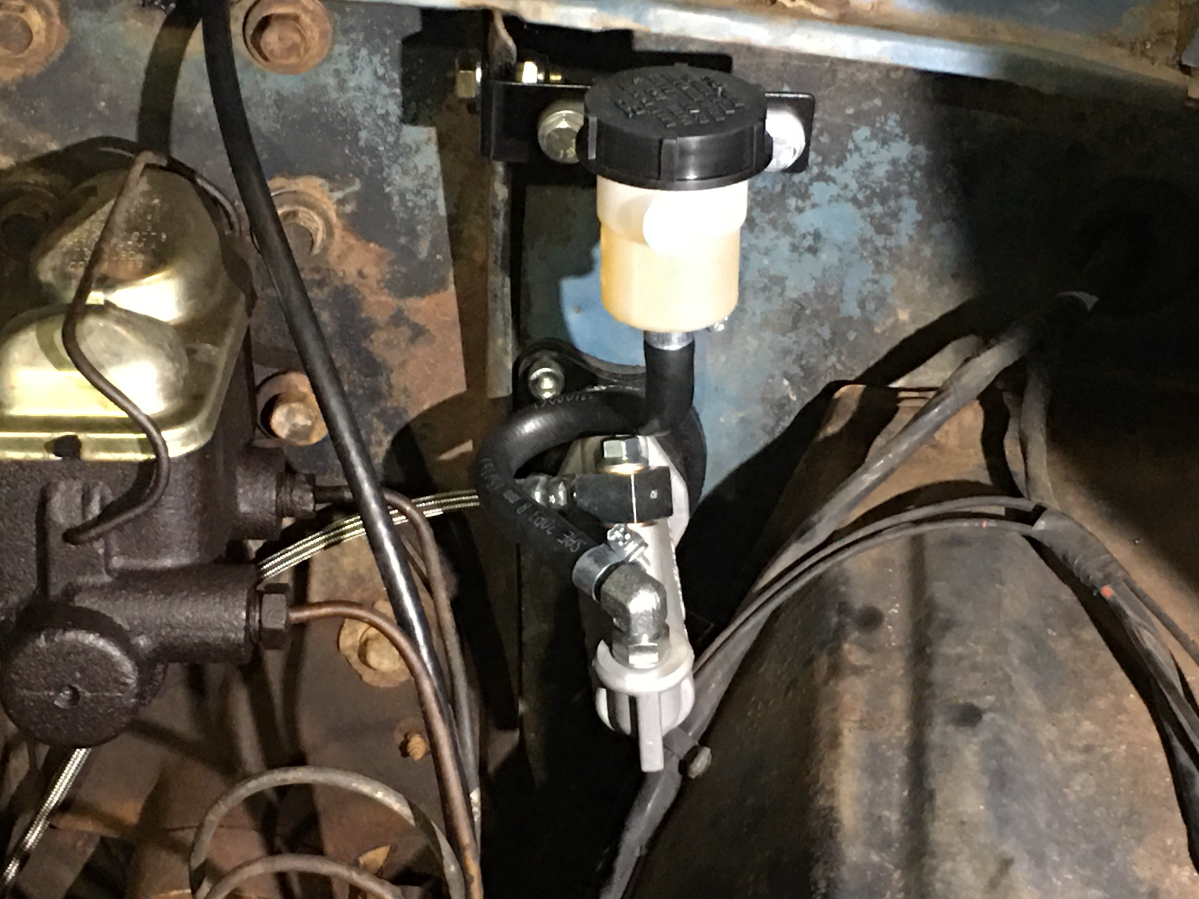
Because hydraulic clutches didn’t exist very much in 1966, we had to adapt some clutch linkage to the stock clutch pedal to operate the slave cylinder. Here’s how that looks on both sides of the firewall.
Before we mated the TREMEC T-56 Magnum trans to our Coyote we wanted to double-check our hydraulic bearing cushion measurement. The cushion measurement sets the desired pressure the SST hydraulic bearing needs to operate correctly. The acceptable cushion measurement is between 0.125 – 0.375 inches. Here are the instructions for the cushion procedure.
With all these parts and information, we moved forward and bolted the transmission to our Energy Suspension mount. One of the last things we needed to consider is the plumbing for the oil filter relocation kit, for which we sourced parts from Earl’s Performance Plumbing. Before planning our oil line routing we spoke with Mike Goodwin, Ford Performance’s tech/info line supervisor, to make sure we did this correctly. The Coyote engine relies heavily on the oiling system to run its hydraulic systems like the camshaft-phasers, lash adjusters, timing chain tensioners, and most importantly the lubrication of all the bearing surfaces. We know that oil volume is important to maintain proper lubrication, so we wanted to speak with Mike about some best practices. He suggested that we use lines that were no smaller than -12, use quality fittings, and stay away from 90-degree fittings if possible (since a 90-degree fitting can represent a flow restriction, which is potentially a bad thing when it comes to oil supply).
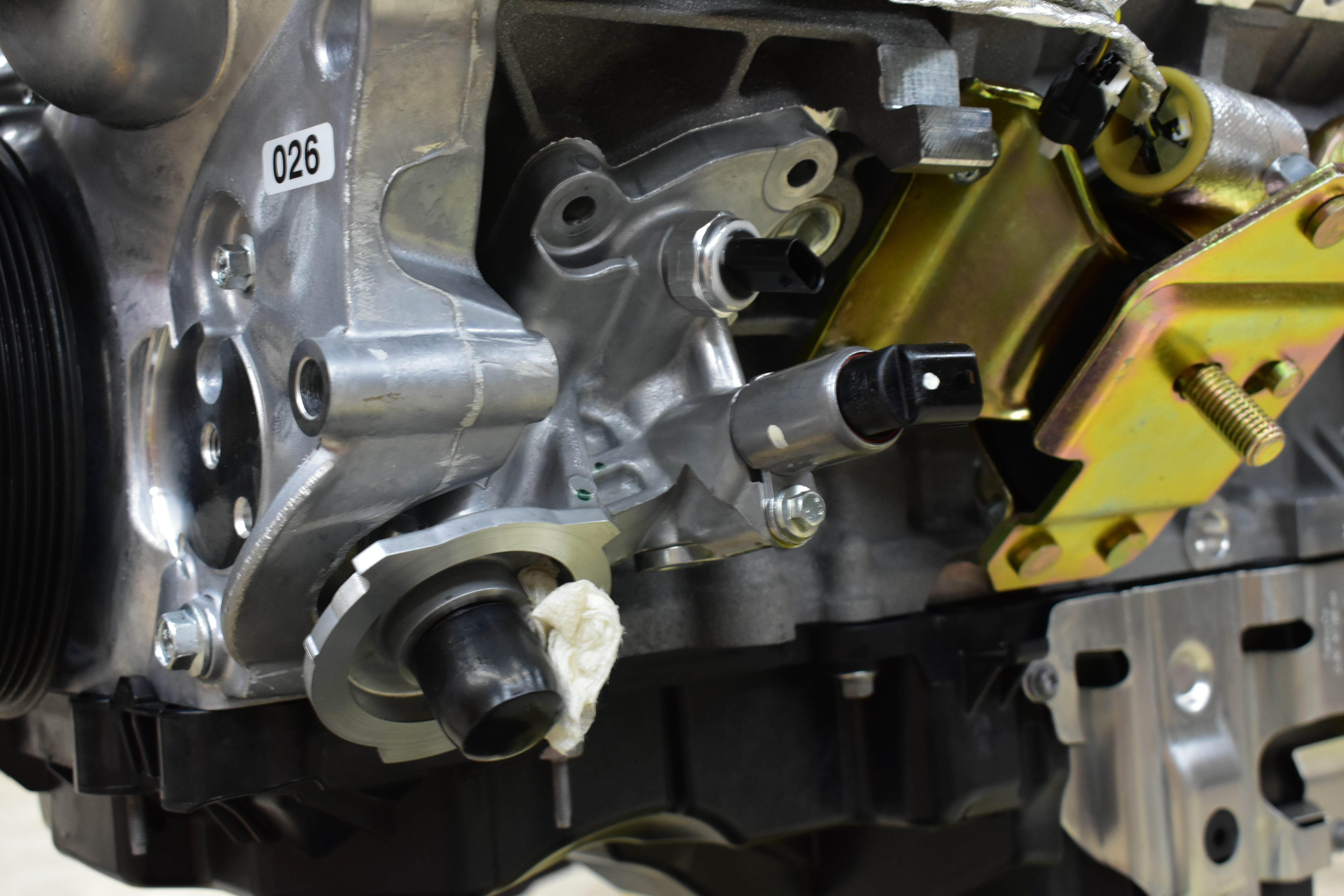
This shows us removing the factory oil filter housing because we need more clearance in that area.
We plan to autocross and road race this truck and therefore depend on properly controlled oil feed—for example in sustained cornering, we want to make sure volume is not compromised. Sometimes large radius bends like the 90’s can create a restriction during those driving conditions. Most importantly when plumbing the oil lines, make sure you route the OUT to IN and OUT to IN between the adapter on the engine block and the filter relocation mount. Failure to do this will result in low or 0 psi of oil pressure, causing damage to your brand-new engine. And nobody wants that to happen!
Earl's Oil Filter Adapter Parts List
- Earl’s Billet Remote Oil Filter Mount - Part# 2077ERL
- Earl’s -12AN to 7/8s-14 O-ring fittings - Part# AT985013ERL
- Earl’s Ultra Pro fittings
- Part# 620112ERL - Straight
- Part# 624512ERL - 45 degree
- Part# 626012ERL - 60 degree
- Earl’s Ultra Pro PTFE hose - Part# 681012ERL

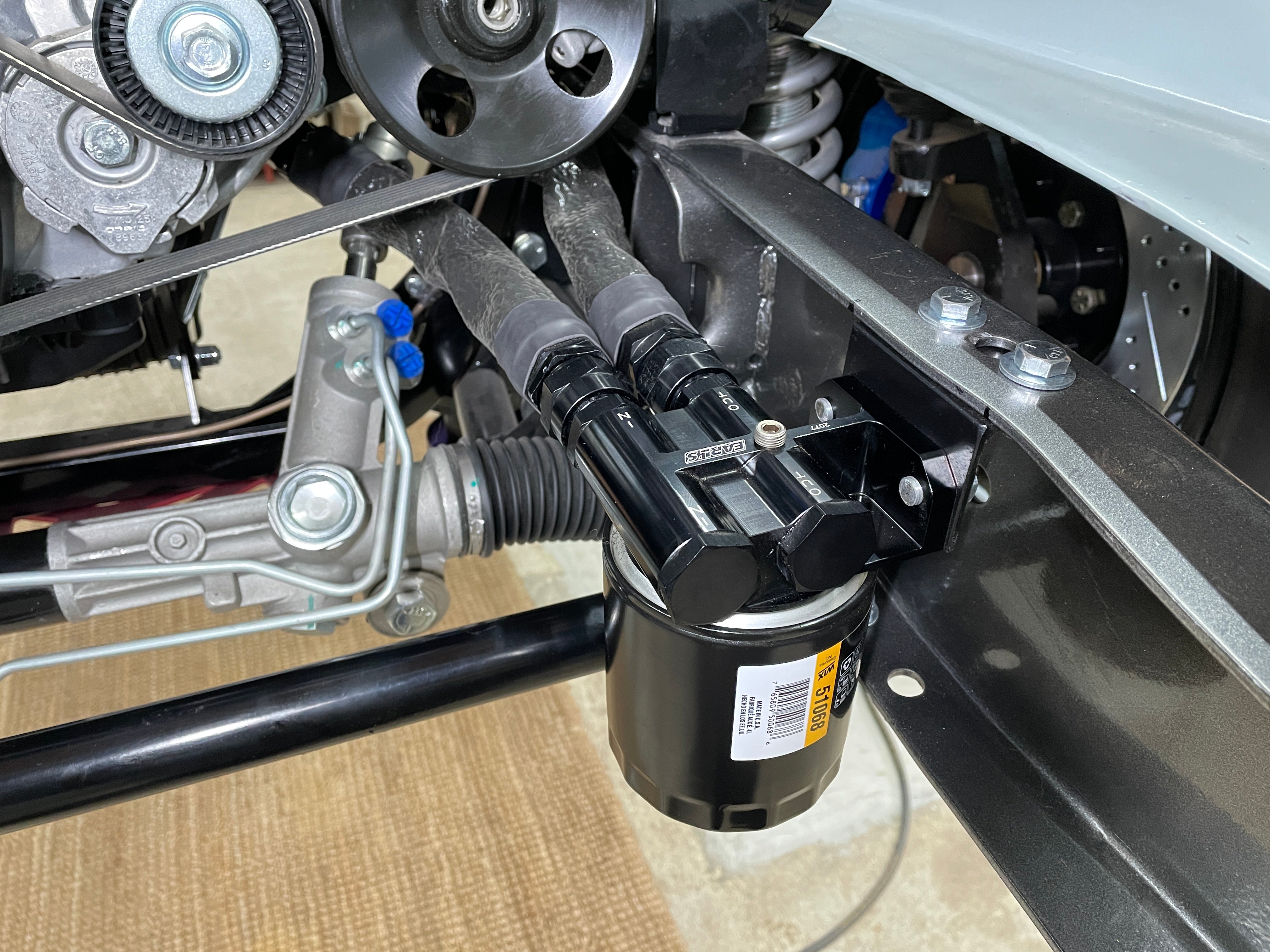

The stock oil filter housing is in the way and needed to be replaced, so we went to Earl’s Performance Plumbing for the goodies, then talked to Mike Goodwin on Ford Performances’ tech line. He said, “The Coyote engine relies heavily on the oiling system to run its hydraulic systems like the camshaft phasers, lash adjusters, timing chain tensioners and most importantly the lubrication of all the bearing surfaces.” He then recommended using lines that are at least -12AN in size and to used quality fittings devoid of 90-degree turns, which present a flow obstruction. Here is how the kit and lines look installed on the Coyote.
Like we said, this wasn’t a particularly difficult swap if you have everything ahead of time and don’t have to make 107 last-minute trips to the parts and hardware store, and take your time with wiring in and setting up the Control Pack. Once you’ve got all of that handled, it’s just a matter of swinging the heavy parts (engine and trans) in and bolting them in place.

Ivan is using the Melling MPL-201 Engine Priming Tank to prime the engine before its first fire. He did this to protect the bearings and other surfaces just in case we didn’t get it to fire on the first few tries. This ensures everything is well lubricated and no premature bearing damage is caused. If you’ve never heard of this Priming Tank, read about it here.

To create more underhood clearance and safety, we installed a remote battery kit prior to running the Control Pack and harness. We used Level 7’s part for that kit and mounted it on the frame under the bed of the truck.
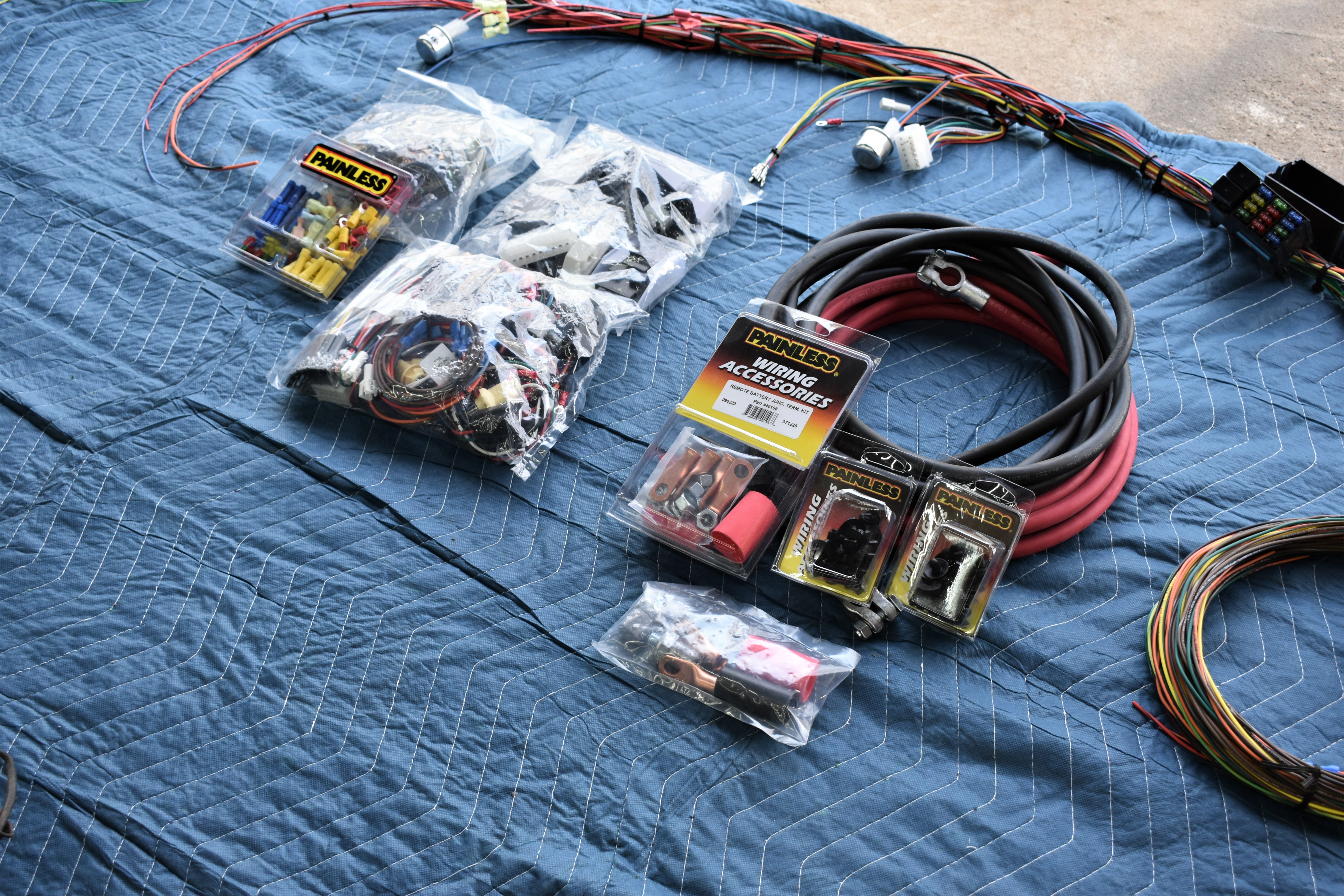
Then we relied on Painless Performance for a wiring harness and the various connectors needed to wire in the battery system.
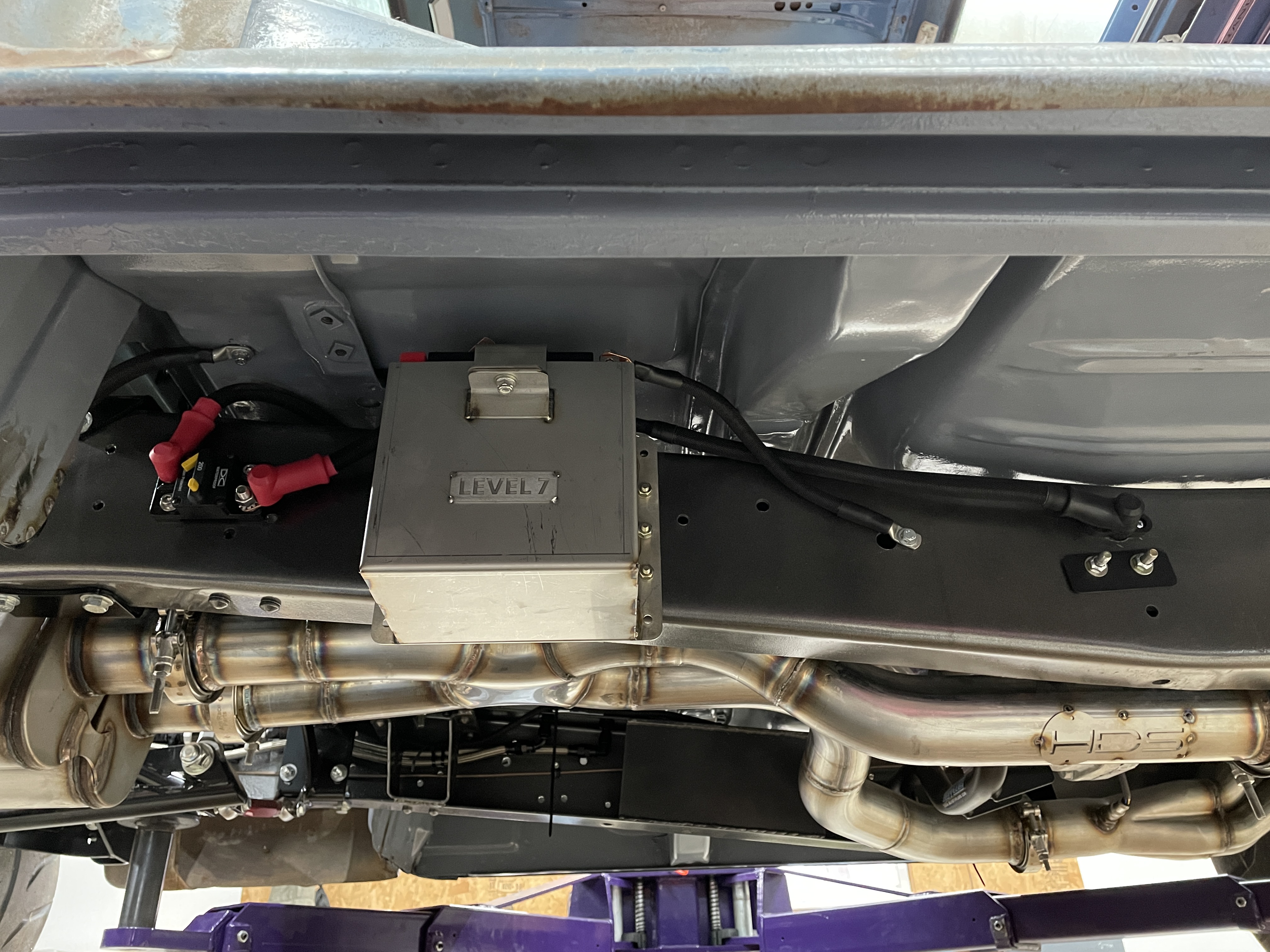
This is where we mounted the battery and main power supply block.
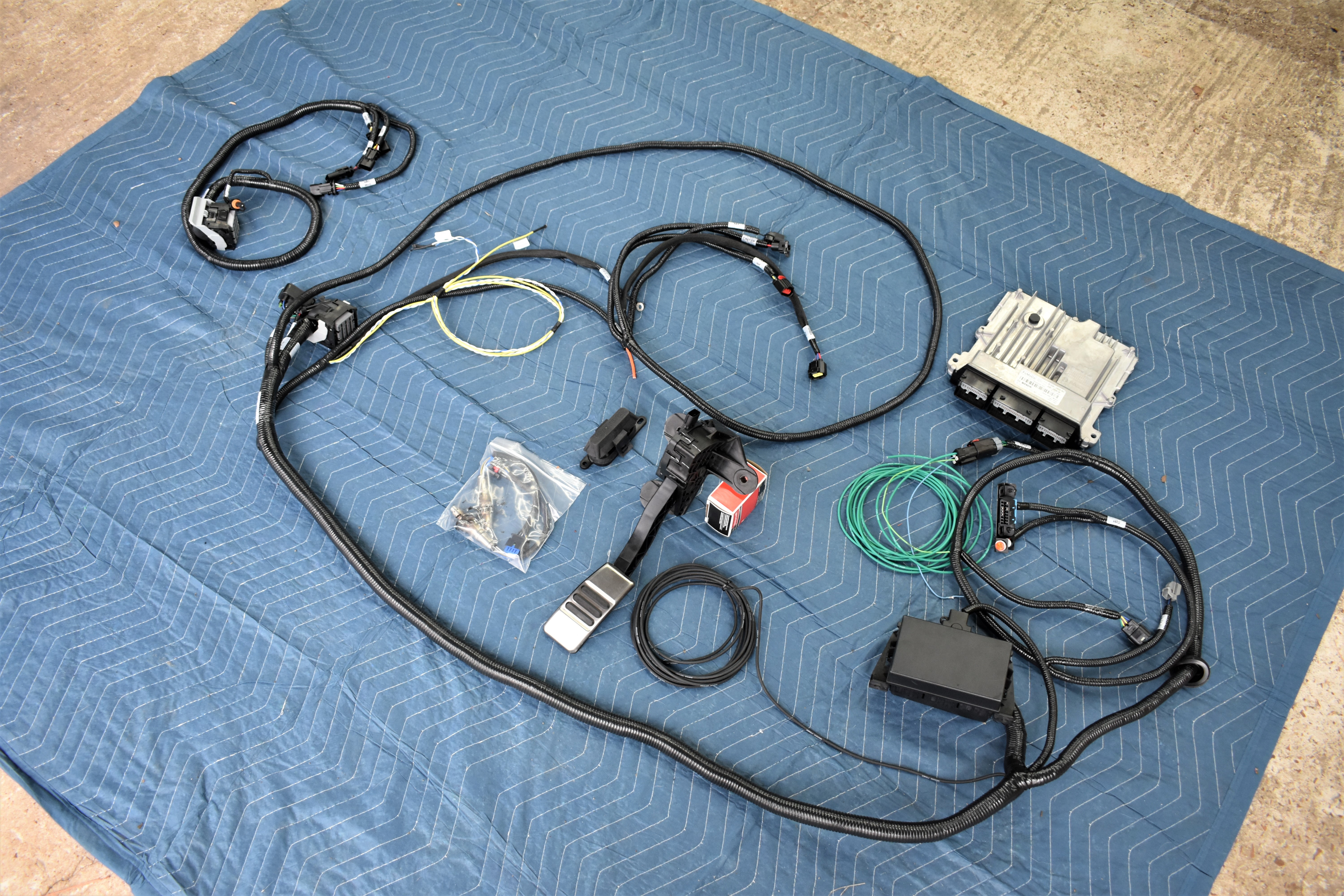
Here’s the Control Pack out of its box. It’s everything you need to hook the Coyote up and get it running as fast as possible with no tuning issues. Notice the electronic throttle pedal—modern EFI engines do not use any more throttle linkages to control them.
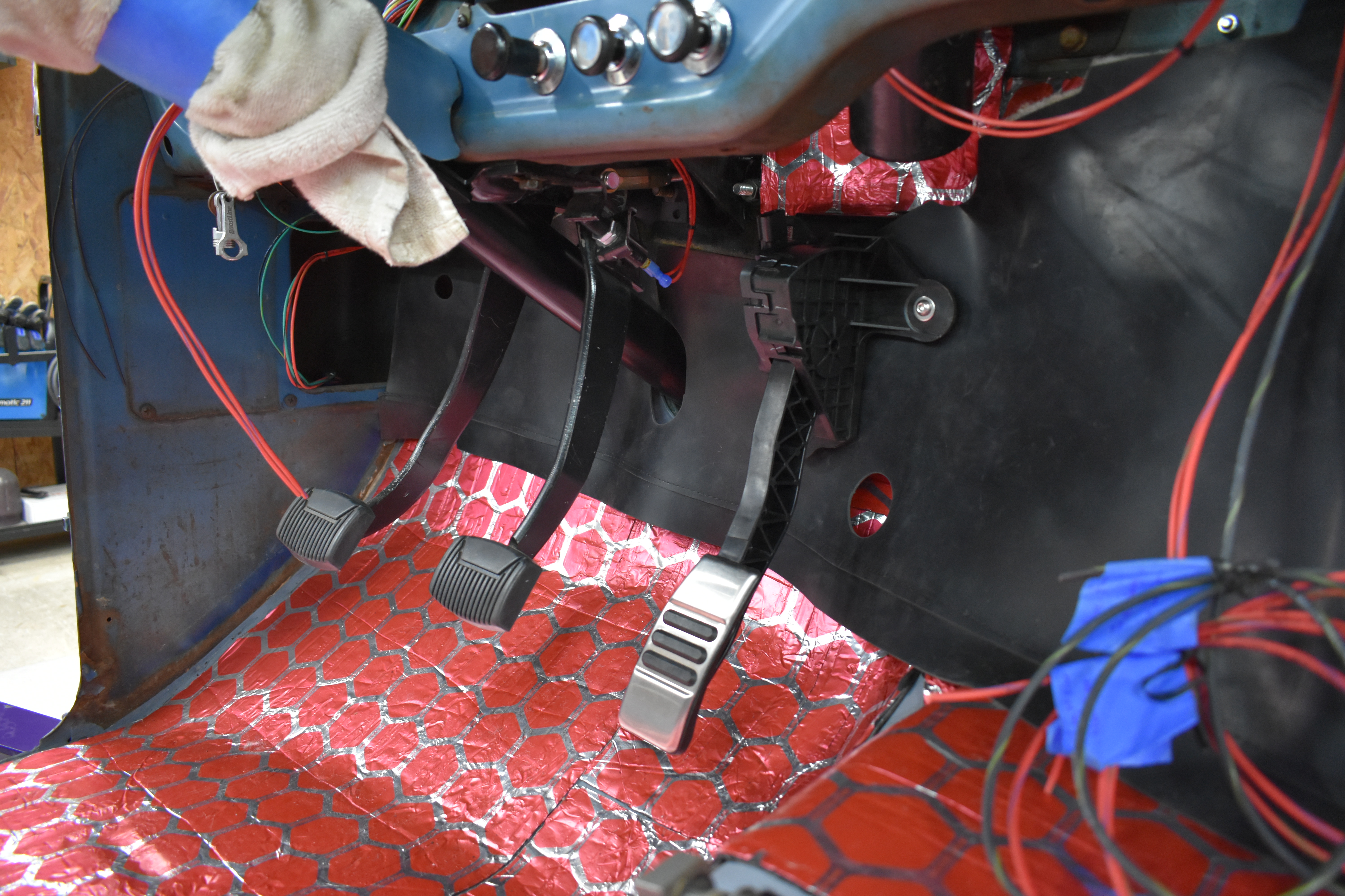
The throttle pedal is a “drive-by-wire” meaning that it processes how much throttle the driver needs and sends appropriate signals to the ECU to control the engine’s load and RPM. It’s pretty easy to mount, even on an F100.
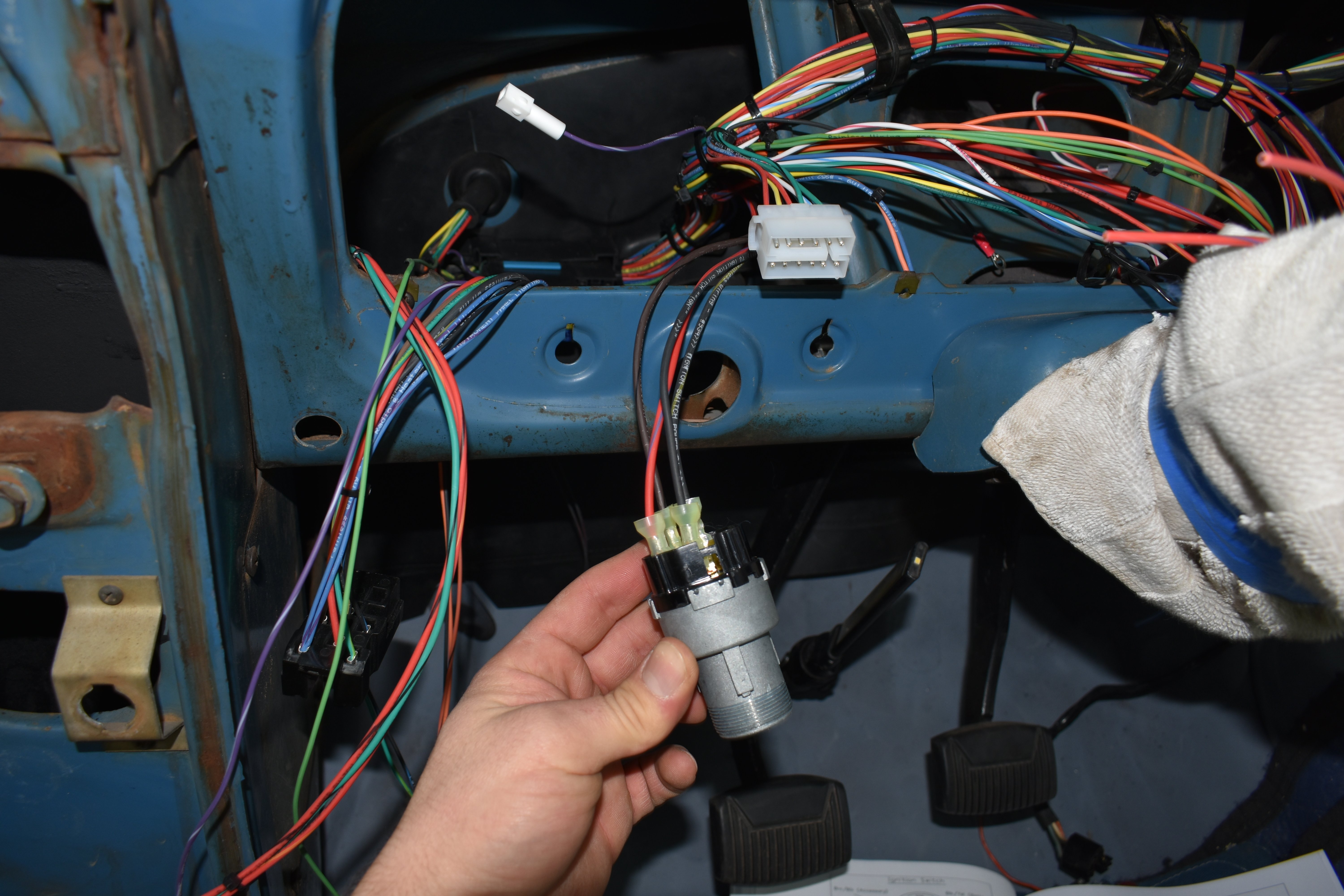
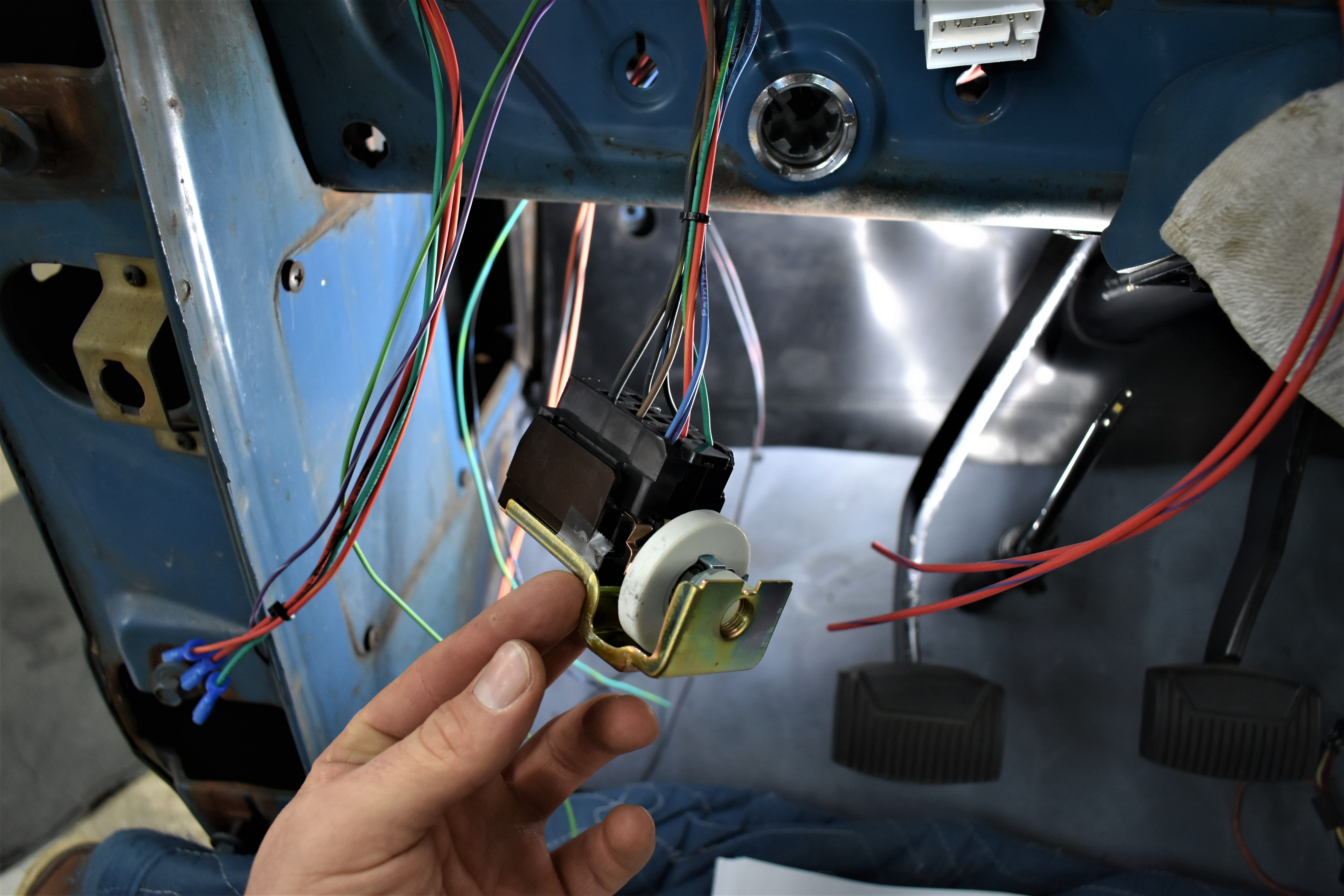
Part of hooking up the Control Pack involves tying it into the truck’s new wiring harness. Here we’re hooking up the ignition switch and windshield wiper control.
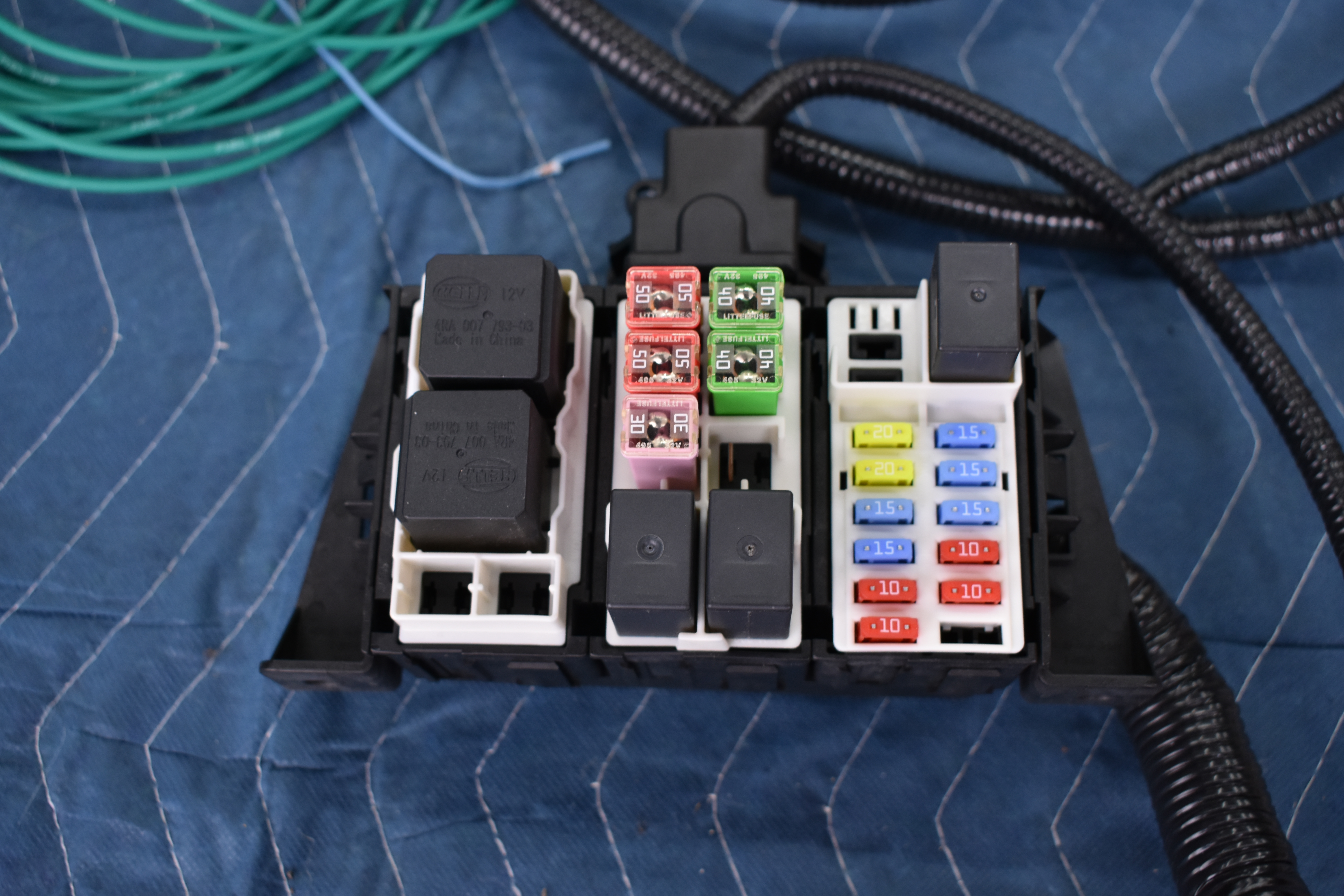
The Control Pack comes with this new fusebox carrying all modern fuses (thank GOD for no more glass fuses!) that we mounted in the engine compartment.

Here’s where we mounted the aforementioned fusebox, using the factory hole in the firewall to reach the accelerator pedal.
After that, it was a simple plugging in of all the wiring harness connectors, including those for the injectors. Take your time with this step and make sure you follow the directions that came with the Control Pack.

Here are our hand-drawn instructions on how to wire the fuse box in order to start the engine when it first starts to crank. Thankfully, our Coyote cranked on the first few times around so, apparently, we wired it correctly!